OPERATION
4-19
Example – Excessive Vcc Loads
See Section 4.5 for a preferred method of tracing current. However, if the PCB tracks are very thick (i.e.
very low resistance) then the following method is applicable.
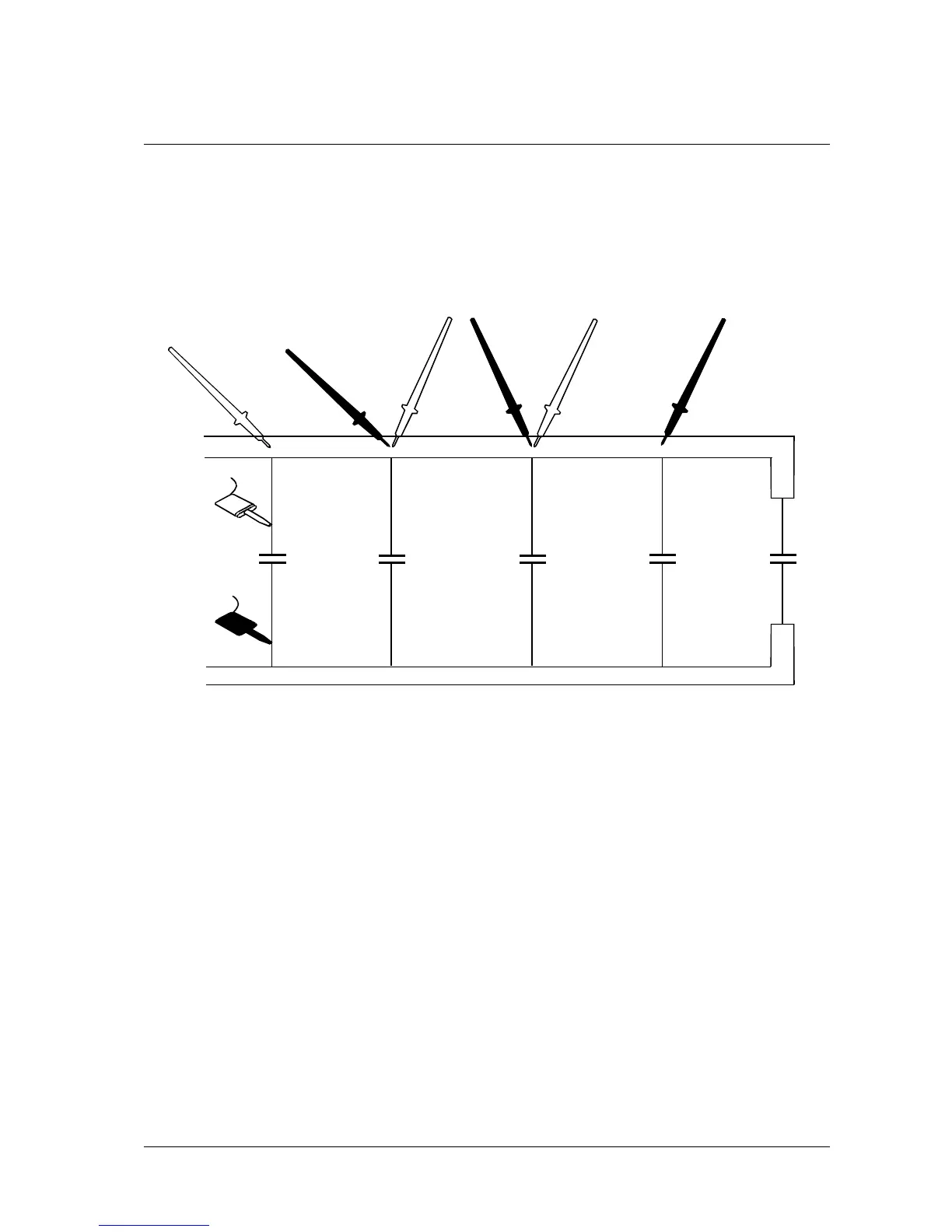
Consider the board shown in Figure 4-10 where the Vcc supply is being loaded.
Assume the fault is static.
A
BC
D
C2
C1
Vcc
GND
DRIVE SOURCE
C3 C4 C5
Figure 4-10 Use of Track Voltage Measurement
• Connect the Drive Source leads across the Vcc and ground connections of the
board.
• Press 2mV and set the DRIVE SOURCE control to maximum.
• The path of the Drive Source current can now be followed to locate the faulty device.
• Using the Needle Probes, measure the voltage between A and B. The reading is
1.257mV indicating high current flow.
• Measure the voltage between B and C. The reading is 1.118mV suggesting
approximately the same current flow.
• Measure the voltage between C and D. The reading is 0.018mV i.e. a low current,
suggesting that C3 has gone low resistance.
• Note that if the Drive Source leads had been connected across C3, all voltage
measurements would be zero. If this happens, the solution would be to move one of
the leads, e.g. to C2, giving a PCB track drop leading to C3.
Artisan Technology Group - Quality Instrumentation ... Guaranteed | (888) 88-SOURCE | www.artisantg.com