OPERATION
4-11
Example – Excessive Vcc Load
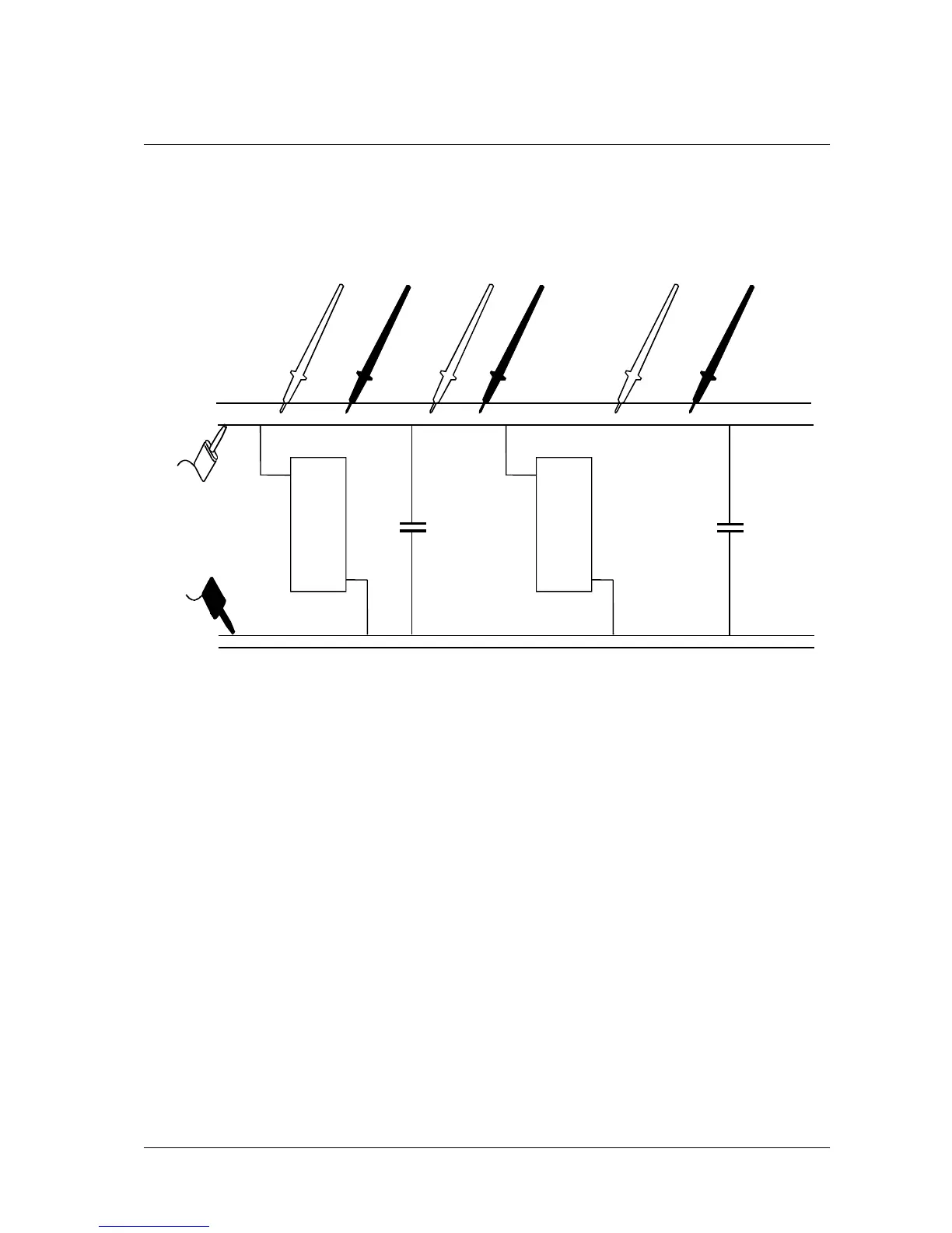
Consider the board shown in Figure 4-5 where the Vcc supply is being loaded. Assume the fault is static.
A
BCDEF
U1
U2 C2
C1
Vcc
GND
DRIVE SOURCE
Figure 4-5 Excessive Vcc Load
• Connect the Drive Source leads across the Vcc and ground connections of the PCB.
• Press 200mA and set the Drive Source control to maximum.
• The path of the Drive Source current can now be followed to locate the faulty device.
• Using the Needle Probes, measure the current through the track AB at approximately
90mA.
• Measure the current through CD at approximately 90mA, i.e. approximately the same.
• Then measure the current through EF at approximately 5mA. This suggests that
85mA is flowing into U2, and that this is the device loading down the supply.
Artisan Technology Group - Quality Instrumentation ... Guaranteed | (888) 88-SOURCE | www.artisantg.com