ELECTRICAL
10.2
SPECIAL TOOLS
PART NUMBER TOOL
DESCRIPTION
PV --43568 Fluke77 Digital
Multimeter
2870836 Battery
Hydrometer
2870630 Timing Light
8712100 or 8712500 Tachometer
ELECTRICAL SERVICE
NOTES
Keep the following notes in mind when diagnosing an
electrical problem.
GRefer to wiring diagram for stator and
electrical component resistance
specifications.
GWhen measuring resistance of a
component that has a low resistance
value (under10 Ohms), remember to
subtract meter lead resistance from
the reading. Connect the leads
together and record the resistance.
The resistance of the component is
equal to tested value minus the lead
resistance.
GBecome familiar with the operation of
your meter. Be sure leads are in the
proper jack for the test being
performed (i.e. 10A jack for current
readings). Refer to the Owner’s
manual included with your meter for
more information.
GVoltage, amper age, and resist ance
values included in this m anual ar e
obtained with a Fluk et 77 Digital
Multimet er (P V--43568).This
meter is acceptable for use when
diagnosing elec tr ical problems.
Readings obt ained wit h other
meters may differ.
GPay attention to the prefix on the
multimeter reading (K, M, etc.) and
the position of the decimal point.
GFor resistance readings, isolate the
component to be tested. Disconnect
it from the wiring harness or power
supply.
TIMING CHECK
PROCEDURES
1. The ignition timing check hole is in the starter
recoil/magneto housing. Remove the check plug.
NOTE: The ignition timing marks are stamped on the
outside of the flywheel. Ignition timing must be
inspected with the engine at room temperature (68°F
/20° C).
2. With the transmission in neutral, start the engine
and set engine speed to 5000 +/- 200 RPM.
3. Direct the timing light at the ignition timing check
hole and check the ignition timing. NOTE: Do not
allow the engine to warm up. The timing will retard
approximately 2° when the engine is warm.
Flywheel
Rotation
32
Timing
Pointer
30°±2° BTDC@5000RPM
28
Stator Adjustment
Stator Adjustment
If the ignition timing is not within the specified range,
adjust the stator plate position as described below.
1. Remove the magneto housing.
2. Remove the flywheel.
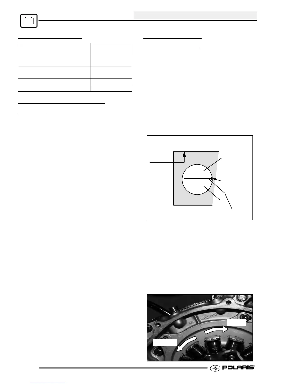
3. Loosen the stator plate screws and adjust the
stator plate position. NOTE: Moving the stator
plate clockwise retards (delays) the ignition
timing. Moving the plate counterclockwise
advances it.
Advance
Retard
 Loading...