19
4.3 Microlight / Home built / G.A.
In general the same as for ultralights with particular care taken for ignition screening and
exposure to rain.
5 BEFORE BEGINNING INSTALLATION
Again check through the supplied parts list.
5.1 Installation parts identication
All connectors are supplied for installation of this transceiver. Parts include a J001 socket
and backshell. Certied aircraft must use approved materials.
5.2 Transceiver installation and removal
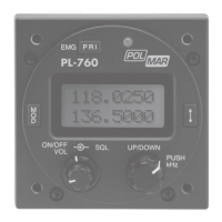
The following section describes the proper installation and removal of the PL-760 transceiver.
5.3 General
General
The following information is provided as a guide for installation in uncertied aircraft. If the
s provided as a guide for installation in uncertied aircraft. If the s provided as a guide for
installation in uncertied aircraft. If the s provided as a guide for installation in uncertied
aircraft. If the PL-760 is to be installed in a certied aircraft the installation must be done
by a certied repair station.
5.4 Pin connections
Note: If you intend using a dynamic mike (non amplied) you must provide amplication.
A simple 2 transistor amplier with gain control will do.
The backlight can be adjusted and dimmed. (Refer to user setting of page 10).
5.5 Mechanical installation
Carefully measure the proposed mounting site for clearance. Allow for rear cabling and
connectors. Use the template supplied to carefully drill a 58mm hole.
Drill the mounting holes (4mm)
The mounting holes support the weight of the transceiver and should not be oversized.
Run all wires that will be required for your particular installation.
Following are the recommended congurations for use in Gliders and Ultralights:
5.6 Electrical installation
Single seat sailplanes:
Power, speaker, microphone (prefer electret), PTT located on control column, backlight
switch or volume (for viewing)
Two place sailplanes:
Additional wiring should include the memory toggle switch for the rear seat, rear PTT
switch and microphone.
Motor Glider:
Jack for headset microphone and speaker.
Ultralights / Microlights:
Power, Speaker (not for open cockpit design), PTT located on control column, headset
microphone (prefer electret), backlight switch or volume, antenna coax type RG58U
(recommend vertical 1/4 wave antenna with ground plane).
Tandem/ side by side:
Additional rear seat PTT and headset wiring, memory toggle switch, intercom switch.
•
•
•
•
•
•
•
•
•