Polycom® RealPresence® Group Series Media Center Setup Sheet
10
1
4
Polycom
®
RealPresence
®
Group Series Media Center
with Dual 42” AIO Displays
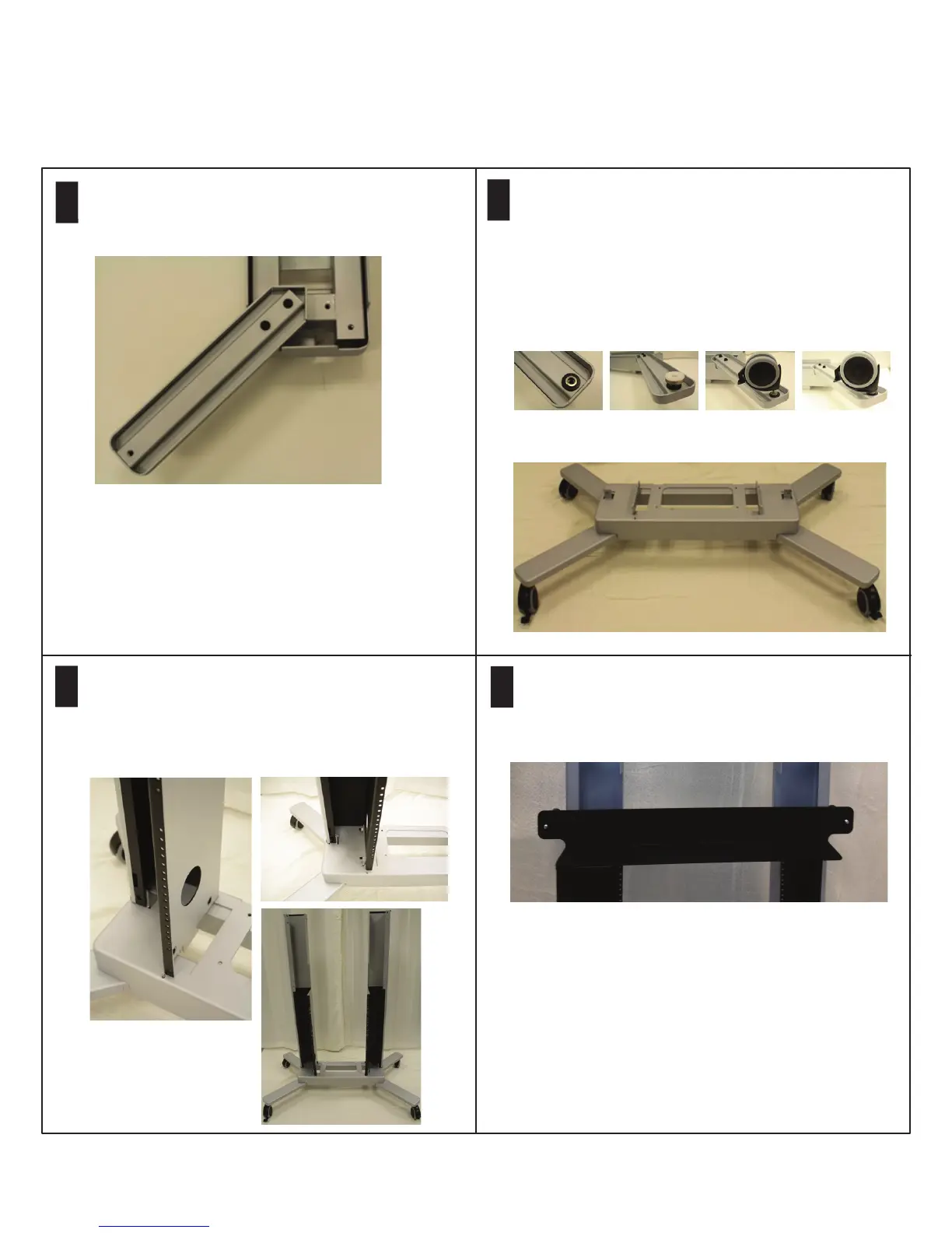
Remove the base from packaging and flip the base over.
Attach the four legs to the base using two M10 x 50
flanged socket head cap screws per leg.
3
Place the left vertical support on the base, aligning the
holes in the base with the holes in the bottom of the
vertical support. Attach the vertical support to the base
using three M10 x 25 flanged socket head cap screws per
vertical support. Do not fully tighten. Repeat with the
right vertical support.
Install the lower display rail by aligning the holes in the
display rail with the holes in the vertical supports. Attach
with four M10 x 25 flanged socket head cap screws. Do
not fully tighten.
2
With the assistance of another person, flip the base over
and lock the front casters.
Install the supplied floor glides on the legs using one flat
washer and one split lock washer per glide. Ensure that the
flat washer is closest to the leg surface. Alternatively,
install the optional casters on the legs. The locking casters
must be installed on the front legs, which are located on the
side of the base with no slots. Attach the casters using one
flat washer and one lock washer per caster. Ensure that the
flat washer is closest to the leg surface. Pull the caster
up to fit the wrench underneath to tighten the hardware.
After tightening, push the caster back down.
Front Side with
Locking Casters
Note: For the RealPresence Group Series wall-secured option, refer to the Polycom RealPresence Group Series Wall-Secured
Setup Sheet.
 Loading...