0DNLQJ0HDVXUHPHQ WV
lation. A higher displacement measurement range must be selected which
then, however, provides worse resolution of the vibration. The best AC resolu-
tion can be maintained however, by periodically resetting the counter and thus
suppressing unwanted DC drift of the signal.
The CLEAR signal does not necessarily have to be provided externally but
can in the simplest case be taken from the VELOCITY OUTPUT itself. Each
zero crossing of a rising velocity signal then resets the displacement decoder.
This requires however a certain quality of the velocity signal. If it is too noisy,
the displacement signal becomes unstable. As the CLEAR input has a rela-
tively low input impedance, an amplitude error of -5% to -10% is induced at
the velocity output in this type of operation (refer to section 7.1.5).
7UDFNLQJ ILOW HU
The correlations shown in section 4.2.2 for the tracking filter also apply in
principle for the displacement measurement. If the range limits shown in
figure 4.1 are exceeded the tracking filter loses lock and induces phase jumps
in the input signal which make the displacement signal discontinuous.
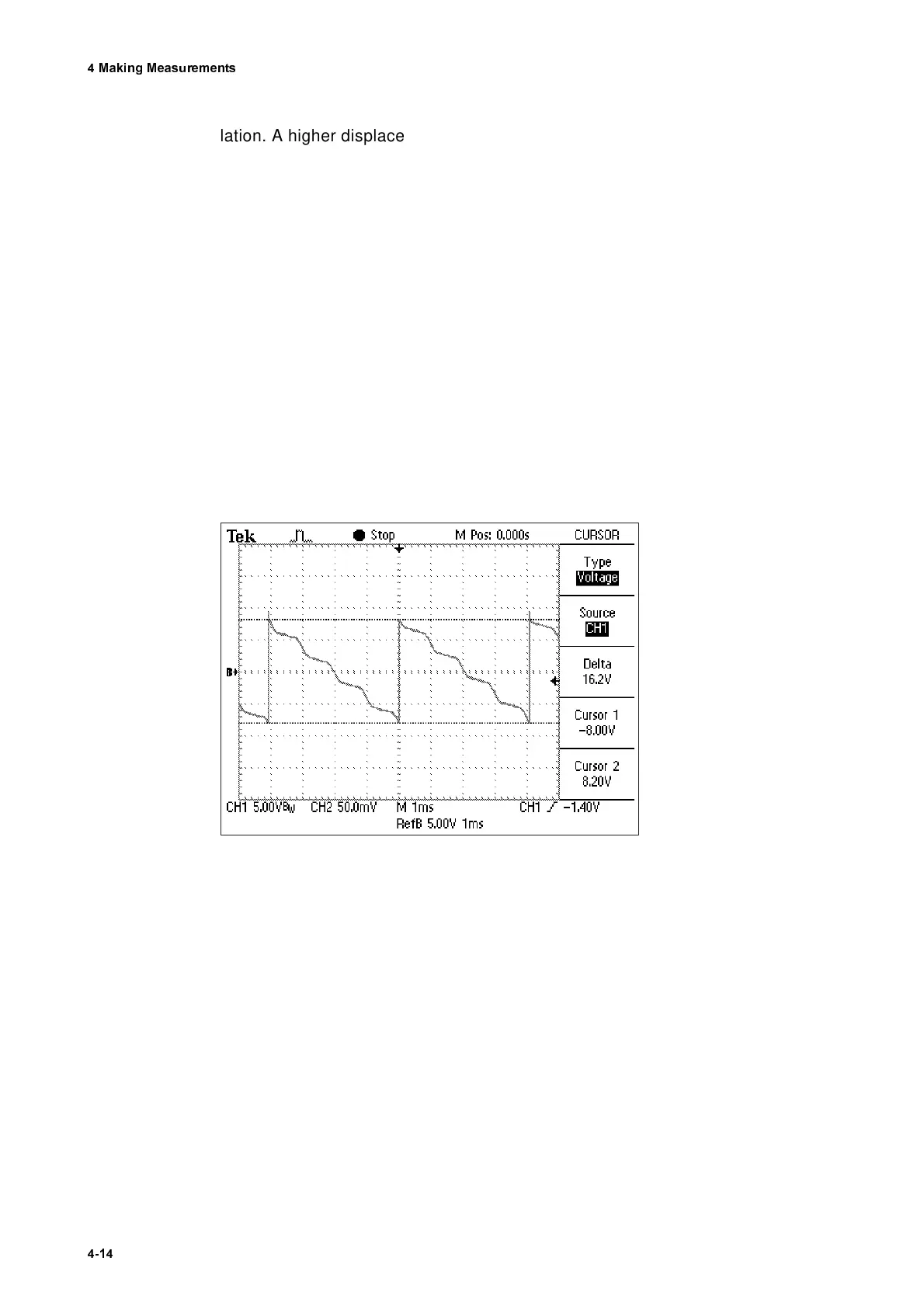
The oscilloscope trace in figure 4.8 shows the distorted displacement signal
of a sinusoidal vibration at an acceleration where the tracking filter loses lock.
In this case the velocity signal should be evaluated and the most suitable set-
ting for the tracking filter should be determined with the aid of figure 4.1.
Figure 4.8: Displacement signal when the tracking filter loses lock