0DNLQJ0HDVXUHPHQ WV
In all velocity measurement ranges the L
ED
OVER on the front of the control-
ler lights up if either the positive or negative end of range is exceeded. As a
general rule, the next highest measurement range should then be selected.
Please note however, that the L
ED
is activated by very short overrange
already which could be caused by noise spikes. In such cases the velocity
measurement range can be retained as long as it is suitable for the amplitude
of the required signal. Observing the signal on the oscilloscope will provide
clarification on this (refer to section 4.1.3).
7UDFNLQJ ILOW H U
The tracking filter is used to improve the signal-to-noise ratio of the input sig-
nal from the sensor head. This is advantageous to bridge short dropouts in
particular, which always occur due to the speckled nature of the light scat-
tered back from the object. The bridging capability is generally better with a
high time constant SLOW, however it may not be possible to follow highly
dynamic signals any more. In this case FAST or OFF has to be selected. The
best setting therefore has to be determined from case to case or be estimated
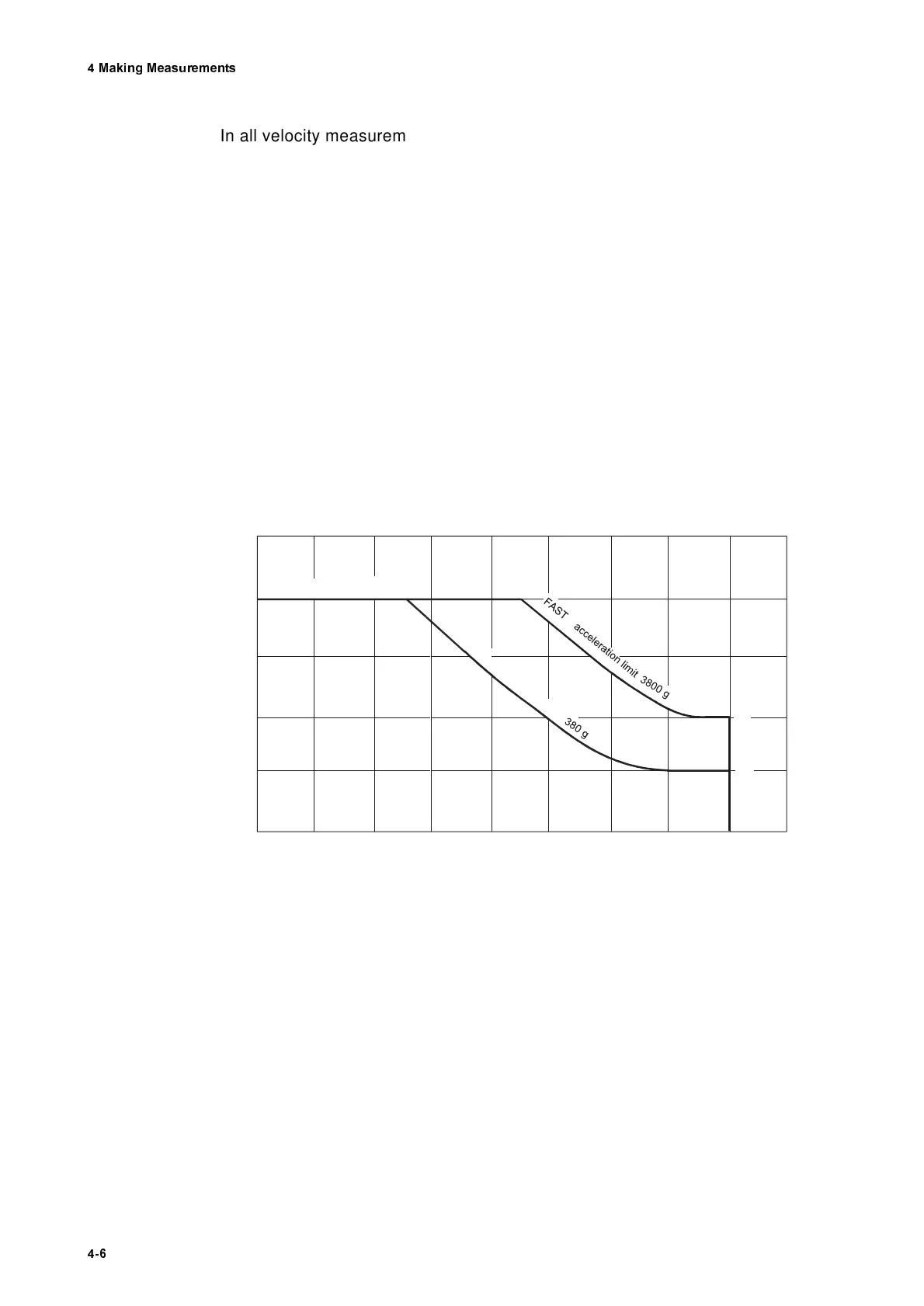
based on the range diagram in figure 4.1. The range diagram shows the
dynamic limits for both settings of the tracking filter, plotted versus the fre-
quency.
A constant velocity limit of approximately 3m/s is characteristic for the lower
frequency range. If the velocity exceeds this value, the tracking filter can gen-
erally not be used and has to be switched off. For special applications a track-
ing filter can be installed for which this velocity limit does not apply. This is
however coupled at worse noise suppression.
In the medium frequency range, the velocity limit changes over to become an
acceleration limit i.e. the velocity limit decreases inversely proportional to the
frequency (refer to equation 4.2).
In the upper frequency range, a constant velocity limit becomes effective
again.
Figure 4.1: Range diagram of the tracking filter
V e lo c ity / m /s
10
3
1
0.3
0.1
0.03
Frequency / kH z
0 .0 1 0 .0 3 0 .1 0 .3 1 3 1 0 3 0 1 0 0 3 0 0
velocity lim it 3 m /s
S L O W a c c e le ra tio n lim it
frequency lim it 100 kH z