Automatic boiler for wood pellets
Instructions for installation and operation
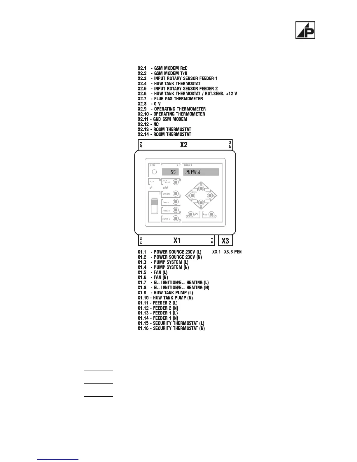
4.2.1 Connection of connectors of the control unit
Figure number 3 - Connection of connectors of the control unit
Interconnection with the ambient is ensured by two connectors – X
1
and X
2
.
The
connector X
1
is used to connect the supply voltage and all power elements (motors of feeders,
fan, circulation pump, etc).
The
connector X
2
connects the operating (boiler's) thermometer, emergency thermostat, indoor
thermostat and other low-voltage inputs.
The
connector X
3
forms the null bridge for mutual interconnection of shielding conductors PEN.
Dimensions of the connectors are different and they are provided with mechanical keys against mix-
up. The system also enables easy and quick replacement of the control unit in case of any failure and
prevents from mix-up of wires during possible repairs.
10