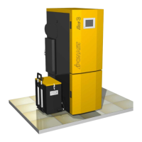
Automatic boiler for wood pellets
Instructions for installation and operation
10. GUARANTEE AND LIABILITY FOR DEFECTS 37
Guarantee conditions 37
Records of performed repairs 38
Picture part 39-46
Directory information -consuption wood pellets for boiler family KP 47
Setting Control Unit from productions 48-49
Technical information - accessories 50-59
LIST OF FIGURES:
Fig.n. 1 Diagram of the product including description of the main parts 8
Fig.n. 2 Control unit of the boiler 9
Fig.n. 3 Connection of connectors of the control unit 10
Fig.n. 4 Block diagram of the control unit 11
Fig.n. 5 Control panel 12
Fig.n. 6 Block diagram of operation of the control unit 13
Fig.n. 7 Tank to heat service water (HUW) 20
Fig.n. 8 Digital indoor thermostat with a weekly programme 20
Fig.n. 9 Recommended draught of the chimney 22
Fig.n. 10 Installation dimensions of boilers 23
Fig.n. 11 Ceramic reflector 24
Fig.n. 12 Parts of the ceramic grate 25
Fig.n. 13 Ceramic shield 25
Fig.n. 14 Recommended wiring diagram of boiler 38
Fig.n. 15 Recommended wiring diagram of boiler 39
Fig.n. 16 Recommended wiring diagram of boiler – cascading wiring 40
Fig.n. 17 Examples of fuel bins, placement of products and requirement on dimensions 41
Fig.n. 18 Wiring - option for supply: 3+PE+N, 50 Hz, 400/230 V, TN-CS 42
Fig.n. 19 Wiring - option for supply 3+PE+N, 50 Hz, 400/230 V, TN-S 43
Fig.n. 20 Schema wiring el. ignition + el. heating 44
Fig.n. 21 Schema wiring electromotive control 4-way valve 44
Fig.n. 22 Wiring room thermostat with weekly programme and independent drive heating HUW 45
Fig.n. 23 Working principle The Boiler in mode modulation 45
Fig.n. 24 Directory information - consuption wood pellets for boiler family KP 46
LIST OF TABLES
Table 1 Thermal and technical parameters of products 6
Table 2 Solid harmful substances in combustion 6
Table 3 Technical parameters of products 6
Table 4 Electrical parameters of products 6
Table 5 Fuel and its parameters 6
Table 6 Setting Control Unit from productions 48-49
3