7
ENGLISH
Using the Lock-Off (Fig. A, C)
WARNING: To reduce the risk of injury, Always wear
proper eye [ANSI Z87.1 (CAN/CSA Z94.3)] and hearing
protection [ANSI S12.6 (S3.19)] when operat- ing this
tool.
WARNING: Do not keep trigger depressed when tool
is not in use. Keep the lock-off switch rotated to the
right (OFF) when the tool is not in use. Serious personal
injury may result.
WARNING: Lock-off trigger, disconnect air line from
tool and remove fasteners from magazine before
making adjustments. Serious personal injury may
result.
Each PORTER‑CABLE nailer is equipped with a trigger lock‑off
switch
1
which when rotat‑ ed to the right, prevents the tool
from actuating.
When the switch is centered, the tool will be fully operational.
The trigger should always be locked off whenever any
adjustments are made or when tool is not in use.
Proper Hand Position (Fig.F)
WARNING: To reduce the risk of serious personal injury,
ALWAYS use proper hand position asshown.
WARNING: To reduce the risk of serious personal
injury, ALWAYS hold securely in anticipation of a
suddenreaction.
Proper hand position requires one hand on the main
handle
11
.
OPERATION
WARNING: To reduce the risk of serious personal
injury, turn unit off and remove air supply before
making any adjustments or removing/installing
attachments or accessories. An accidental actuation
can causeinjury.
Preparing the Tool (Fig.B)
WARNING: Read the section titled IMPORTANT
SAFETY INSTRUCTIONS at the beginning of this
manual. Always wear proper eye [ANSI Z87.1 (CAN/
CSA Z94.3)] and hearing protection [ANSI S12.6 (S3.19)]
when operating this tool. Keep the fastener pointed
away from yourself and others. For safe operation,
Trigger
WARNING: Keep fingers AWAY from trigger when
not driving fasteners to avoid accidental firing. Never
carry tool with finger on trigger. In bump action mode
(contact actuation mode) tool will drive a fastener if
contact trip is bumped while trigger is pulled.
In accordance with the ANSI Standard SNT‑101‑ 2015, the
PORTER‑CABLE nailers are assembled with a sequential
action trigger. For a replacement trigger contact your
authorized service center or call 1‑888‑848‑5175.
The red trigger with imprinted on the side, (Cat.# 600852 kit)
is the single sequential action trigger and causes the tool to
operate in this mode.
The black trigger with imprinted on the side, (Cat.# 600851
kit) is the bump action trigger and per‑ mits the tool to be
actuated in this manner.
For defining the use of the sequential action trigger and
bump action trigger, see the Actuating Tool section of
thismanual.
To Replace Sequential Trigger
Trigger Removal (Fig. A–D)
1. Lock off trigger.
2. Remove air from the tool.
3. Remove rubber grommet
13
from end of dowel pin
14
.
4. Remove dowel pin.
5. Remove trigger assembly from trigger cavity under the
handle of the tool housing.
Trigger Installation (Fig. D)
1. Select appropriate trigger assembly to be installed on
the tool.
2. Insert the trigger assembly into trigger cavity.
3. Ensure that trigger spring
15
is placed around the
trigger valve stem.
4. Align the holes of the trigger with the housing holes,
then insert the dowel pin
14
through the entire
assembly as shown.
5. Push the rubber grommet
13
onto the end of the dowel
rod as shown.
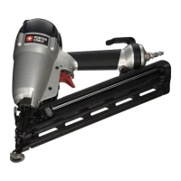
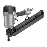
FASTENER SPECIFICATIONS
Model FN250C DA250C
Length 1"-2 1/2"
(25.4 mm - 65 mm)
1" - 2 1/2"
(25.4mm - 65mm)
Shank Diameters 16 gauge 15 gauge
Nail Stick Angle straight 34
complete the following procedures and checks before
each use of thefastener.
NOTICE: These nailers are designed to be used
withoutoil.PORTER-CABLE
• Before you use the tool, be sure that the compressor
tanks have been properlydrained.
• Wear proper eye, hearing and respiratoryprotection.
• Remove all fasteners from the magazine.
• Check for smooth and proper operation of contact trip
and pusher assemblies. Do not use tool if either assembly
is not functioning properly. NEVER use a tool that has the
contact trip restrained in the upposition.
• Check air supply: Ensure air pressure does not exceed
operating limits; 70to 120p.s.i.g., (5to 8.5kg/
cm
2
).PORTER‑CABL
• Connect airhose.
• Check for audible leaks around valves and gaskets. Never
use a tool that leaks or has damagedparts.