16
1
8
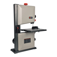
5. Snap two short plastic stops (7) over the end of the
rear table extension tubes (2). Make sure the locating
pin in the location seats fit into the matching holes in
the extension tubes. (Fig. Q)
Fig. Q
INSTALLING THE BLADE (FIG. R, S, T)
To avoid injury from an accidental start, make sure
the switch is in the OFF position and the plug is not
connected to the power source outlet.
1. Remove the table insert (1) by snapping out from
the hole (8). Raise the blade arbor to the maximum
height by turning the blade elevation handwheel
clockwise. (Fig. R)
Fig. R
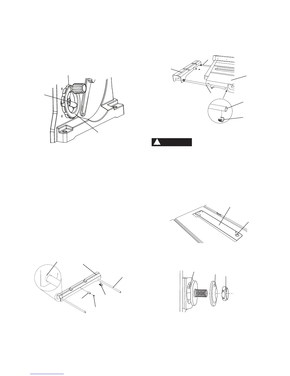
2. Remove the arbor nut (2) and outer blade flange (3).
(Fig. S)
Fig. S
3. Place the blade onto the arbor (4) with the blade teeth
pointing forward to the front of the saw. (Fig.
T)
4. Make sure the blade fits flush against the inner
flange.
5. Clean the outer blade flange (3) and install it onto the
arbor (4) and against the blade. (Fig. T)
2
7
2
3
1
4
WARNING
!
4
3
2
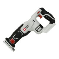
INSTALLING THE BLADE TILTING HANDWHEEL
(FIG. O)
1. Bag " A "
_
Attach the blade tilting handwheel (1) to
the blade tilting rod on the right side of the saw in the
same manner as you attached the elevation hand
wheel.
2. Attach and tighten the dome nut (2).
Fig. O
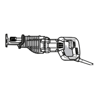
INSTALLING THE REAR TABLE EXTENSION
(FIG. P, Q)
1. Bag " B, C, D "
_
Insert the two rear table extension
tubes (2)
into the rear table extension (1). (Fig. P)
NOTE: They must be inserted into the back
of the extension with the bent end last so that
the bar will hold the extension in place.
2. Snap two long plastic stops (4) over the two rear
table extension tubes (2). Make sure the locating pin
in the black plastic stops fits into the matching hole
in the extension tube. This will ‘lock’ the tube into the
extension. (Fig. P)
3. Insert the rear table extension tubes (2) into the two
extension tube brackets under the table (3).
Fig. P
4. Attach the rubber pad (5) to the inside of the rear
table extension (1). Thread the screw (6) through the
rubber pad with a screwdriver. Do not overtighten the
screw (6). (Fig. Q)
2
1
1
5
4
2
Bend End
6