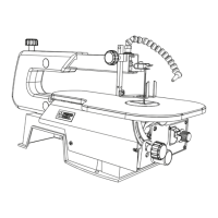
12
ASSEMBLY AND ADJUSTMENTS
● The stand is designed only for use with a scroll
saw.
● Do not climb, sit or stand on the stand assembly.
● Do not use the stand on uneven or unstable
surface.
● To avoid injury, do not connect this scroll saw to
the power source until it is completely assembled
and adjusted and you have read and understood
this instruction manual.
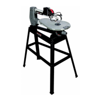
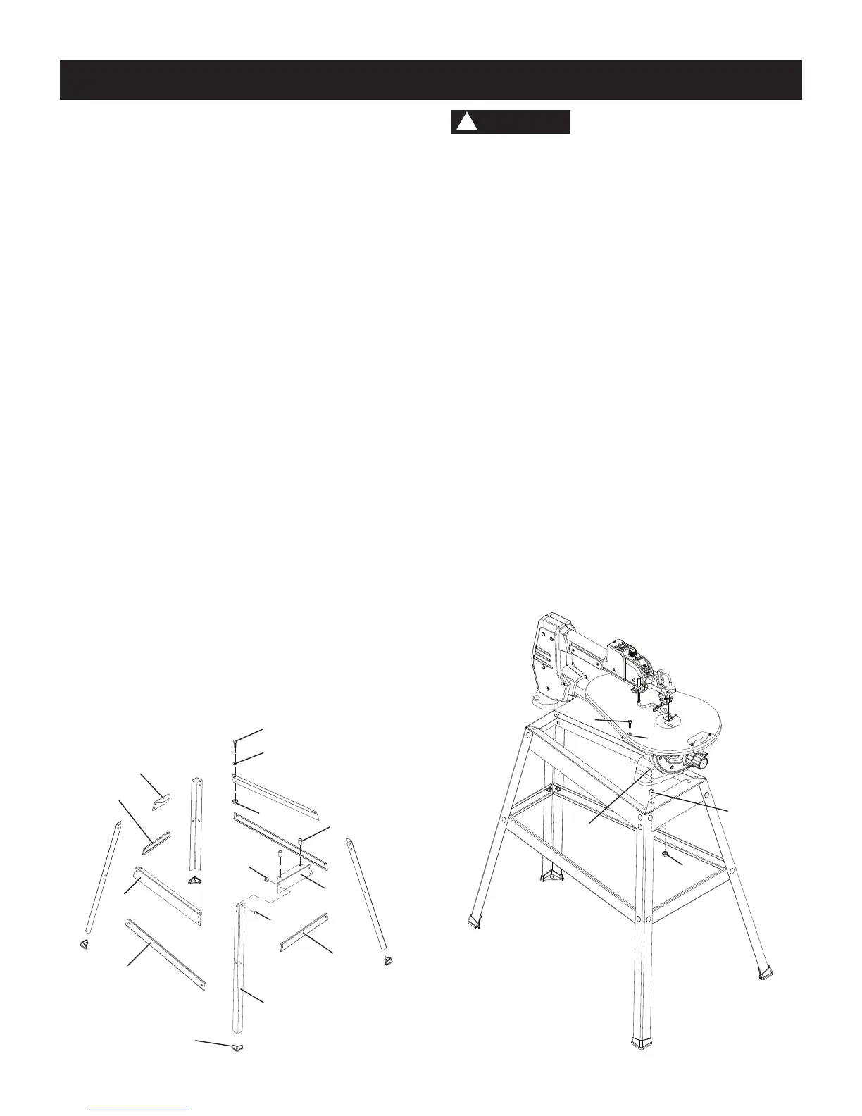
MOUNTING THE SCROLL SAW (FIG. B)
1. To mount your scroll saw to the stand, position the
stand leg on a firm, level surface.
2. Matching the four holes (13) in the scroll saw base
with the holes in the stand leg, place the scroll saw
on the stand as shown below.
3. Secure the stand and saw by the hex bolts (9), flat
washers (10), sleeves (11) and nuts (12) provided
in front mounting holes, and by the hex bolts (9), at
washers (10) and nuts (12) in rear mounting holes.
4. Tighten all four nuts using a 13 mm or adjustable
wrenches.
NOTE: Do not over tighten nuts, it may damage the
saw base.
Fig. B
WARNING
!
9
10
11
13
12
Estimated Assembly Time: 25 - 40 Minutes.
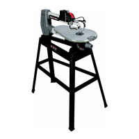
INSTALLING THE STAND (FIG. A)
1. Unpack all parts and group by type and size. Refer
to the table of loose parts list on page 8 & 9 for
correct quantities.
2. Bag "F" & "H" -
Attach one end of front bracket -
upper support (1) to top of leg (2) using one bolt (3)
and nut (4). The stand leg is placed on the outside of
the brackets.
NOTE:
●
The left side of the bracket has only one hole and
the right side has two holes.
●
Only hand tighten at this point. DO not tighten
bolts with a wrench until stand is properly
aligned (see step #8 before tightening).
●
The front and rear stand legs are different in
angles and cannot be mixed.
3. Attach other end of front bracket - upper support (1)
to top of another leg (2) using one bolt (3) and nut (4).
4. Attach the front bracket - lower support (5) to center
the two legs using bolt (3) and nut (4). This completes
the front frame section.
5. Bag "E" & "H" - Assemble rear frame section in
exactly the same manner using the shorter rear
brackets (12 & 13).
6. Bag "C" & "D" - Join the front and rear frame
sections using two brackets upper supports (6) and
two lower supports (7) with bolts and nuts.
7. Bag "G" - Place the four foot pads (8) into the bottom
of each leg. (lightly use a rubber mallet if needed).
8. Place the stand on level surface, adjust all legs to
contact and are at similar angles to the floor. Tighten
all bolts.
NOTE: To avoid rocking, all bolts must be tightened
securely using a 13 mm or adjustable wrench.
Fig. A
9
10
1
5
2
7
6
4
8
3
12
11
14
13
Front
Front Side of
Frame Assembly