12 13
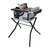
FIG. 3
FIG. 4
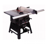
FIG. 2
CORRECT INCORRECT
STYROFOAM
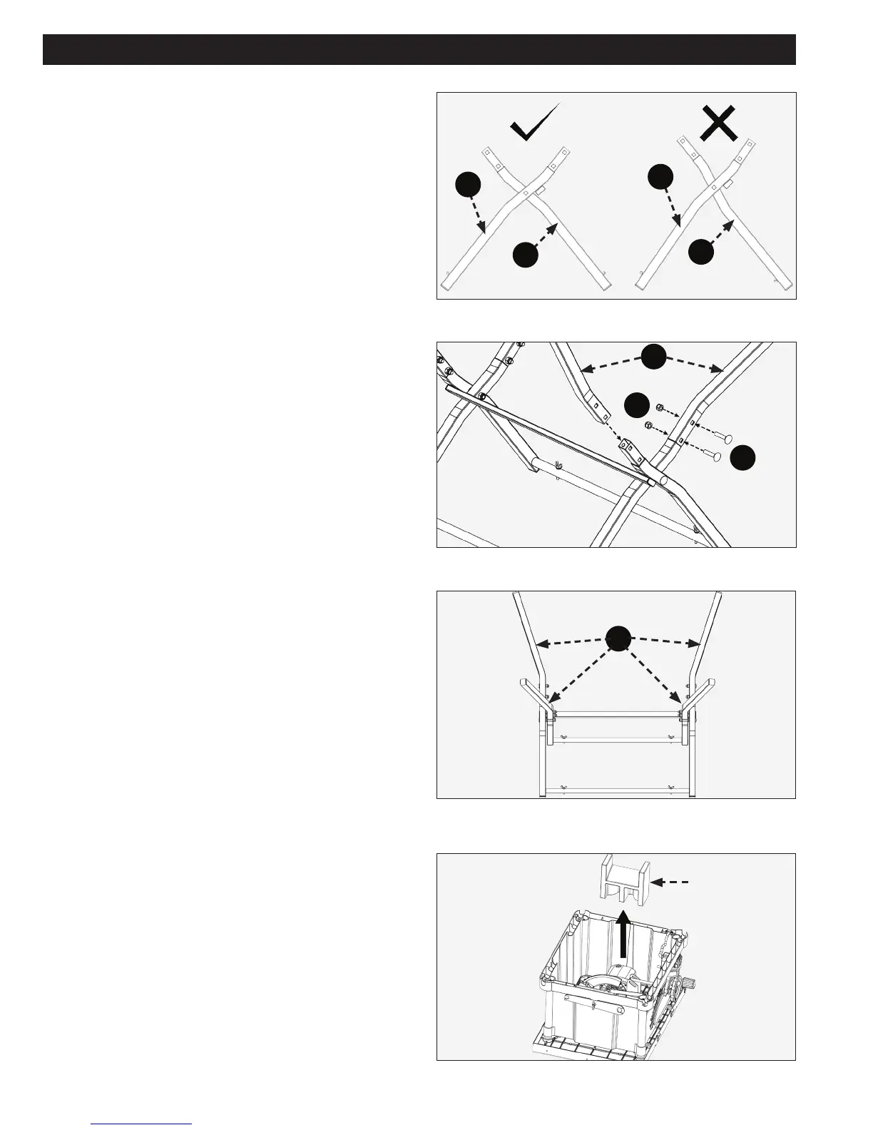
FIG. 5
NOTE: Please refer to (Fig. 2) for correct stand cross
section parts setup.
With assembled cross section stand open, attach legs
(J) to the stand using (8) M8 x 35mm (1 1/2 in.) carriage
bolts (a) and (8) M8 lock nuts (b). Tighten lock nuts to
secure legs to stand. (See Fig. 3)
NOTE: Do not over tighten lock nuts.
See finished assembly of stand in Fig. 4.
NOTE: Before assembling stand to saw, unlock bevel
lock, tilt blade/motor assembly and remove styrofoam
piece from under saw motor. (See Fig. 5)
ASSEMBLY (CONTINUED)
H
H
I
I
J
J
b
a