11
a
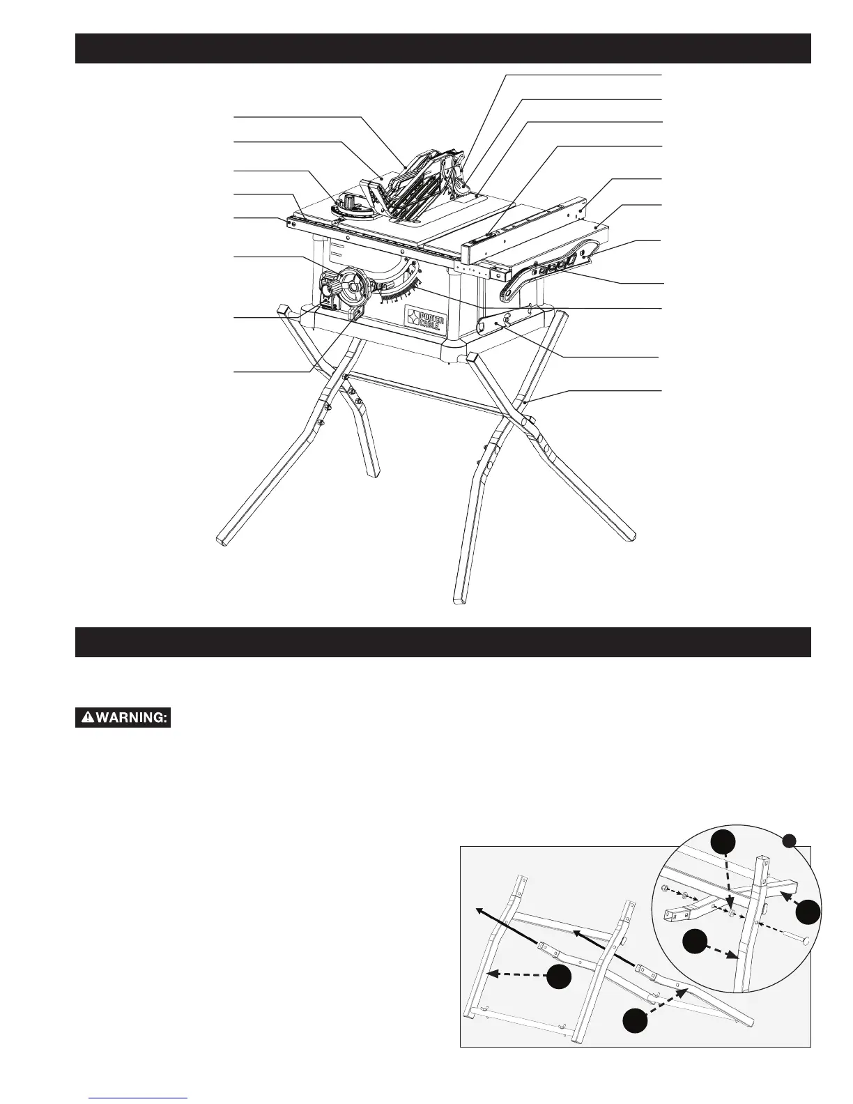
GENERAL PARTS KNOWLEDGE
ASSEMBLY
FIG. 1
STAND ASSEMBLY
Assemble stand part (I) through stand part (H) that
has cross support as shown in (Fig. 1). Secure stand
assembly with M8 x 65mm (2 9/16 in.) hex socket
half round head screw, M8 plastic washer (k), M8 flat
washer and M8 lock nut . (see Fig. 1a)
NOTE: M8 plastic washer is between stand part (H) and
(I).
See Fig. 2 on page 11 for correct stand cross section
parts setup.
The part and hardware names and letters correspond to those used in General Parts Knowledge on Page 11 and the
Shipping Contents on page 9 & 10. The letter designations are also used in the assembly instructions in this manual.
BEVEL SCALE
BLADE WRENCHES
STAND
ON/OFF
SWITCH
BEVEL
LOCK
HEIGHT
ADJUSTMENT
WHEEL
FENCE RAIL
SCALE
MITER GAUGE
BLADE GUARD
TABLE
RIP FENCE
EXTENSION WING
PUSH STICK
HEX/PHILLIPS WRENCH
FENCE LOCK
ANTI-KICKBACK PAWLS
THROAT PLATE
RIVING KNIFE
H
I
H
I
k
• When lifting saw, hold it close to your body while
lifting. Keep knees bent and lift with your legs, not
your back.
• Fully assemble saw with leg assembly prior to use.
• Leg assembly is an integral and necessary part of
the support structure for this saw.
• Do not modify saw, or create accessories not
recommended for use with this saw.
• Do not connect to power supply until assembly
is complete. Make sure power switch is in “OFF”
position before connecting to power supply.
• Avoid contact with blade teeth. Keep blade stored
or lowered when possible.