29
)LJ))
)LJ**
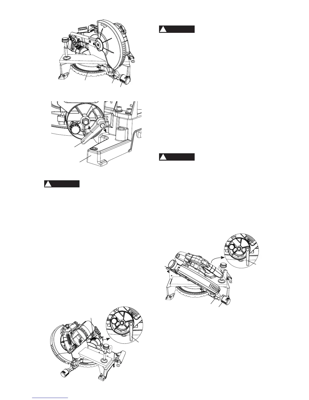
BEVEL CUT (FIG. HH)
1(9(5%(9(/WRWKHULJKWWKLVVDZLV
GHVLJQHGWRRQO\EHXVHGIRUFXWWLQJOHIW
bevel cuts.
:KHQDEHYHOFXWLVUHTXLUHGORRVHQ
the bevel lock handle (1) by turning
it clockwise.
2. Tilt the cutting head to the desired angle,
as shown on the bevel scale (2).
3. The blade can be positioned at any angle,
from a 90° straight cut (0° on the scale)
to a 47° left bevel. Tighten the bevel lock
handle (1) to lock the cutting head in
position.
4. Turn the laser guide on and position the
workpiece on the table for pre-alignment
of your cut.
)LJ++
1
2
3
2
1
COMPOUND CUT (FIG. GG, II)
WARNING
!
1(9(5%(9(/WRWKHULJKWWKLVVDZLV
GHVLJQHGWRRQO\EHXVHGIRUFXWWLQJOHIW
bevel cuts.
A compound cut is the combination of a miter
and a bevel cut simultaneously.
1. Loosen the miter handle (1). Lift up the
positive stop locking lever (2) and position
the table at the desired angle. Release
the positive stop locking lever (2) and lock
the miter handle (1). (Fig. II)
2. Loosen the bevel lock handle (3) and
position the cutting head at the desired
bevel position. Lock the bevel lock
handle (3).
3. Turn the laser guide on and position the
workpiece on the table for pre-alignment
of your cut.
ŏ
7RDYRLGWKHEHYHOORFNKDQGOH
LQWHUIHULQJZLWKWKHPLWHUVDZEDVH
ZKHQWKHULJKWPLWHUDQJOHLVJUHDWHU
WKDQSXOOWKHEHYHOORFNKDQGOH
WRDGMXVWWKHGLUHFWLRQQRWWRSRLQW
GRZQZDUGVKRZQLQ)LJ**
ŏ As the
ULJKW
PLWHUDQJOHLV
JUHDWHUWKDQ
GRQRWFRPELQHZLWKDQ\EHYHO
DQJOHWRSUHYHQWWKHLQWHUIHUHQFH
)LJ,,
3
1
2
WARNING
!
4
5
WARNING
!