15
7RUHGXFHWKHULVNRILQMXU\WXUQXQLWRIIDQGGLVFRQQHFWLWIURPSRZHU
source
EHIRUHLQVWDOOLQJDQGUHPRYLQJDFFHVVRULHV
EHIRUHDGMXVWLQJRUZKHQPDNLQJ
UHSDLUV$QDFFLGHQWDOVWDUWXSFDQFDXVHLQMXU\
(VWLPDWHG$VVHPEO\7LPH0LQXWHV
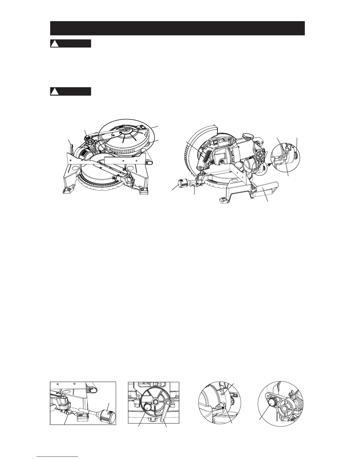
ASSEMBLY INSTRUCTIONS TO RAISE THE CUTTER HEAD (FIG. A, B, C, D, E, F)
7RDYRLGLQMXU\PDNHVXUHDOOSDUWVDUHDVVHPEOHGDQGDGMXVWHGSURSHUO\EHIRUHSOXJJLQJ
WKHPLWHUVDZLQWRDSRZHURXWOHWDQGWXUQLQJLW21
PLACE THE SAW ON A FLAT, STABLE SURFACE.
127(&XWWKHWZRWLHFDEOHVWRUHOHDVHWKHFXWWHUKHDGIURPWKHEDVH
ASSEMBLY AND ADJUSTMENTS
WARNING
!
WARNING
!
#2
Bevel lock
handle
#8
Hold-down latch
Cutting head
Carrying handle
#1
Miter handle
#6
Positive stop
locking lever
#4
Switch handle
#5
Detent block
#7
Positive
stop bolt
#3
Safety
lock pin
STEP 1: Thread the miter handle (1) into the hole located at the front of the table as shown in
)LJV%&
STEP 2:
Loosen the bevel lock handle (2) located behind the base as shown in)LJV$'
STEP 3: Pull out the safety lock pin (3) located next to the bevel lock handle as shown in
)LJ'
STEP 4: Lift the cutting head by the switch handle (4))LJ%to raise the cutting head straight
up just pass the 90° bevel setting.
STEP 5: Rotate the metal detent block (5), located on the right side behind the table
)LJV%(, counterclockwise 180°.
STEP 6: Tilt the cutting head back to 90° and then tighten the bevel lock handle (2). The
positive stop bolt (7) )LJ( will now rest on the detent block (5).
STEP 7: Loosen the miter handle (1), grasp it and lift up the positive stop locking lever (6)
)LJV%& located under the miter handle, to turn the table to 0° as shown on the
miter scale. Retighten the miter handle (1).
STEP 8: Slightly push down the cutting head using the switch handle (4) and pull out the hold-
down latch (8) )LJ) located near the back on the left side of saw. This releases the
cutting head.
)LJ& )LJ' )LJ( )LJ)
1
6
3
2
5
7
8
)LJ$ )LJ%