16
'RQRWXVHWKLVVDZWRFXWDQGRUVDQG
PHWDOV7KHKRWFKLSVRUVSDUNVPD\LJQLWH
VDZGXVWIURPWKHEDJPDWHULDO
)LJ*
,167$//,1*7+(+2/''2:1&/$03
$66(0%/<),*++
CUTTING SMALL OR ROUND MATERIAL
,WVKRXOGEHFXWMXVWOLNHZRRGDQG
CLAMPED OR HELD FIRMLY TO THE
FENCE TO KEEP IT FROM ROLLING. This
LVH[WUHPHO\LPSRUWDQWZKHQPDNLQJDQJOH
cuts.
1. Place the hold-down clamp assembly (1)
into the mounting hole (2) located behind
the fence. The clamp should be facing
toward the back of the miter saw as
shown in Fig. H.
2. The groove on the clamp rod should be
fully inserted into the mounting hole of the
base without being visible. If the groove is
visible, the clamp will not be secure.
3. Rotate the hold-down clamp assembly (1)
180 degrees toward the front of the miter
saw.
4. Loosen the knob (3) to adjust the clamp
XSRUGRZQWR¿UPO\FODPSWKHZRUNSLHFH
5. The hold-down clamp assembly (1) can
be inserted in one of the two mounting
holes (2) located behind the fence on
either side of the base. (Fig. H-1)
NOTE: Place the clamp on the opposite
side of the base when bevelling. ALWAYS
MAKE DRY RUNS (UNPOWERED) BEFORE
FINISH CUTS TO CHECK THE PATH OF
THE BLADE. ENSURE THE CLAMP DOES
NOT INTERFERE WITH THE ACTION OF
THE SAW OR GUARDS.
LOCKING THE CUTTING HEAD (FIG. A, F)
When not in use, the miter saw cutting head
should always be locked in the down position.
1. Pull down the switch handle (4) to place
the cutting head in its lowest position.
2. Push the hold-down latch (8) in.
IMPORTANT: To avoid damage, never carry
the miter saw by the switch handle, the cutting
head or the miter handle. ALWAYS use the
designated carrying handle. (See Figs. B& M)
Ɣ 7RUHGXFHWKHULVNRILQMXU\\RXPXVW
XQSOXJWKHVDZIURPSRZHUVRXUFH
EHIRUHIROGLQJIRUWUDQVSRUWDWLRQRU
VWRUDJH
Ɣ 7RUHGXFHWKHULVNRILQMXU\WXUQXQLW
RIIDQGGLVFRQQHFWLWIURPSRZHU
source
EHIRUHLQVWDOOLQJDQGUHPRYLQJ
accessories,
EHIRUHDGMXVWLQJRUZKHQ
PDNLQJUHSDLUV$QDFFLGHQWDOVWDUWXS
FDQFDXVHLQMXU\
Ɣ 0DNHVXUHEODGHKDVVWRSSHGURWDWLQJ
EHIRUHIROGLQJWKHVDZ
FOLDING THE CUTTING HEAD FOR
TRANSPORTATION AND STORAGE
(FIG. A, B)
1. Keep the cutting head in the up position.
2. Slightly push down the switch handle (4)
and push the hold-down latch (8) into the
locking hole. (Fig. A)
3. Loosen the miter handle (1), grasp it and
lift up the positive stop locking lever (6) to
turn the turntable to the right 55° and then
tighten the miter handle. (Fig. B)
4. Loosen the bevel lock handle (2), tilt the
cutting head
towards left over 90°
and
then turn the detent block (5) clockwise
180
°
to release the positive stop bolt (7).
(Fig. B)
5. Pull out the safety lock pin (3) and grasp
the switch handle (4) to lower the cutting
head towards the right and down until
hearing a “click” sound. (Fig. B)
NOTE: Make sure the cutting head is
locked in position and could not be moved.
6. Tighten the bevel lock handle (2). (Fig. A)
DO NOT STORE MATERIALS ON TOP
2)6$:ZKHQLQWKHIROGHGRUXQIROGHG
SRVLWLRQ
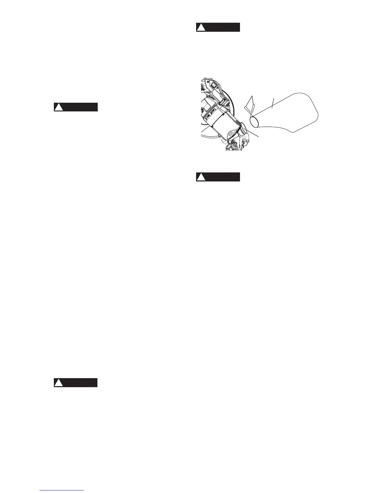
INSTALLING THE DUST BAG (FIG. G)
6TXHH]HWKHPHWDOFROODUZLQJVRIWKH
dust bag (2).
2. Place the dust bag neck opening around
the dust port (3), and release the metal
collar wings (1).
2
1
3
WARNING
!
WARNING
!
WARNING
!
WARNING
!