28
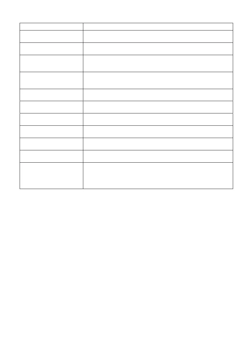
The variables that can be set for the Analogue channels are:
The voltage that will be sent to the sensor channel +V connection when the
sensor is being read. This can be 3.6V, 5V or 21.6V.
The length of time the sensor is powered before the reading is taken. Longer
times lead to shorter battery life.
Engineering value for low (zero) reading. Depending on configuration, this value
will be used when the input is 0mA (when configured to 0-20mA), 4mA (when
configured as 4-20mA) or 0V (when configured as 0-10V)
Engineering value for high (zero) reading. Depending on configuration, this value
will be used when the input is 20mA (when configured to 0-20mA or 4-20mA) or
10V (when configured as 0-10V)
Selects whether the input pin (IN connection) mode and scaling is set up for 0-
10V, 4-20mA or 0-20mA
LOLO alarm value (can be overwritten by value1 of Command 3(l) – see section
Error! Reference source not found. for more details)
LO alarm value (can be overwritten by value2 of Command 3(l) – see section
Error! Reference source not found. for details)
HI alarm value (can be overwritten by value9 of Command 3(h) – see section
Error! Reference source not found. for details)
HI alarm value (can be overwritten by value9 of Command 3(h) – see section
Error! Reference source not found. for details)
Callout delay (in minutes) – how long an alarm condition must occur for before
the alarm is sent.
This value, in the engineering units set creates a ‘window’ around each threshold
set on the channel. It is used when you have a noisy input that may trigger a
threshold multiple times if around a threshold value. It should be set to a value
that is larger than the maximum ‘noise’ expected on the input. For example,
sloshing in a water tank could be eliminated using this.