Powered by Safety
®
iv
FlexTrol™ Class E2 Medium Voltage Controllers with
Eaton Contactor
01.4IB.46300
Figures
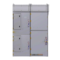
Figure 1 FlexTrol™ 400A & 800A ..................................................................................8
Figure 2 Two-High Vertical Section Rear View (400A) .................................................9
Figure 3 High and Low Voltage Compartments ........................................................10
Figure 4 Eaton Type SL Medium Voltage Vacuum Contactor 400A ..........................12
Figure 5 Eaton Type SL Medium Voltage Vacuum Contactor 800A ..........................13
Figure 6 Isolating Switch Operating Handle .............................................................14
Figure 7 Typical Dimensions for FlexTrol™ ................................................................................15
Figure 8 Recommended Method for Lifting an Indoor Lineup .................................. 19
Figure 9 Typical FlexTrol™ Floor Plans .......................................................................20
Figure 10 Ground Bus Splicing Configuration ............................................................. 25
Figure 11 Insulation of Bus Bar ....................................................................................27
Figure 12 Single Bus Bar Connection Joint ..................................................................27
Figure 13 Double Bus Bar Connection Joint ................................................................28
Figure 14 Tee Connection Joint .................................................................................... 28
Figure 15 Dead End Bus Joint Insulation .....................................................................29
Figure 16 FlexTrol™ - 400A ..........................................................................................30
Figure 17 FlexTrol™ - 800A ..........................................................................................30
Figure 18 Low Voltage Compartment ..........................................................................32
Figure 19 Wire Way .......................................................................................................32
Figure 20 Isolation Switch Interlock ............................................................................35
Figure 21 Mechanical Interlock Verification ...............................................................38
Figure 22 Blown Fuse Indicator ....................................................................................42