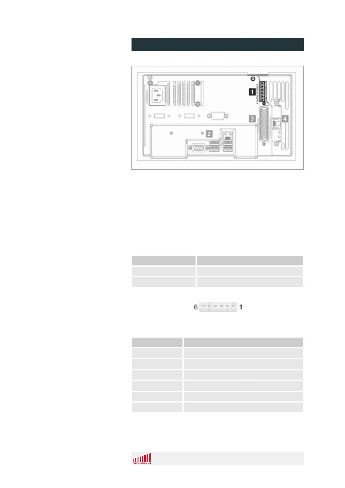
Fig. 31: Safety connector location (model "Analog/SDI")
1 Safety connector X19
For information regarding the safety connector's purpose and
wiring examples see
Ä
Chapter 2.8 “Machine safety” on page 17
and
Ä
Chapter 5.4 “Wiring for machine safety” on page 81.
3.6.1 Safety connector specification
Property Value
Form factor 6 pin, removable screw plug
Maximum contact load 1A / 24V DC
Fig. 32: Safety connector pins
Pin (Fig. 32) Assignment
1 Power ok, common
2 Power ok, normally closed
3 Power ok, normally open
4 CNC ready, common
5 CNC ready, normally closed
6 CNC ready, normally open
Safety Connector Location
Purpose / Wiring
Specification
Pin Assignment
PA 8000 EL CNC control unit
Design and function
24.09.2015 | 56
 Loading...