3.3.1.3 Input schematic
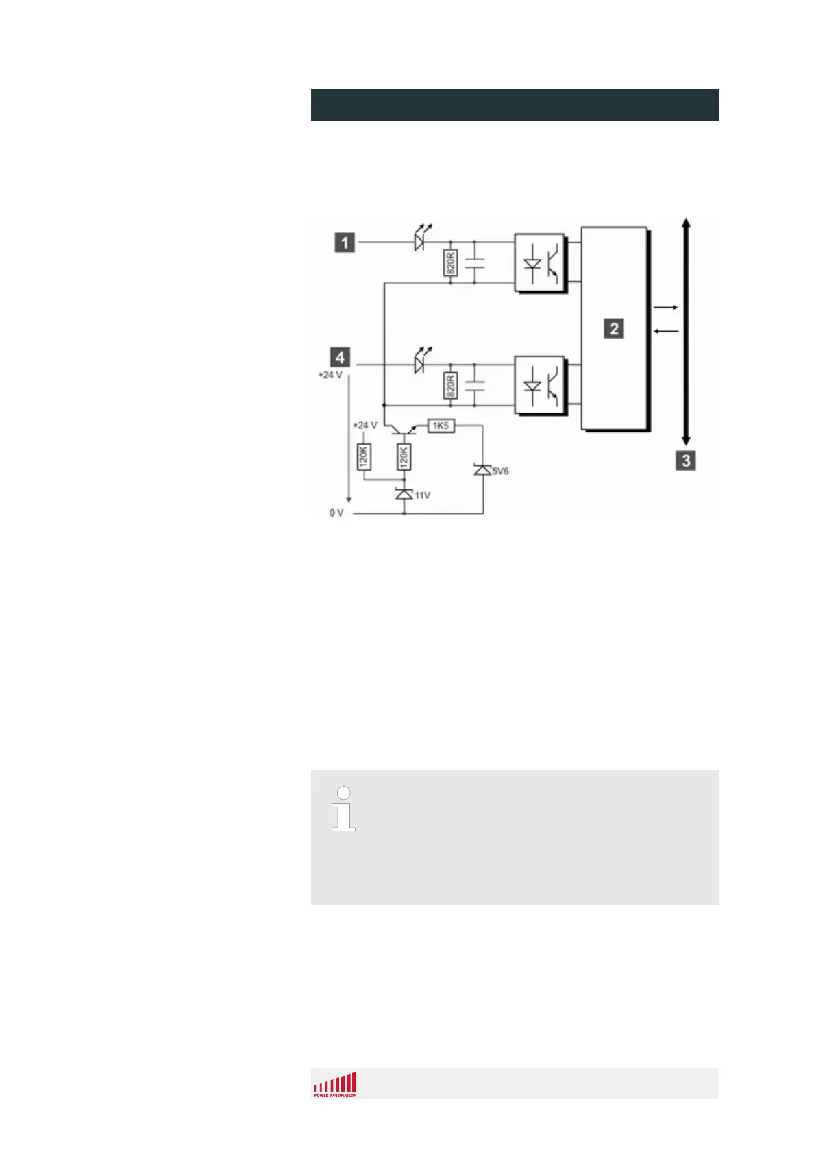
This figure shows how the inputs are realized on each 2416 EL
module.
Fig. 12: Input equivalent schematic
1 Input n+1
2 Logic
3 CNC superbus
4 Input n
3.3.1.4 Handwheel I/O
On each 2416 EL input/output module two special inputs for hand-
wheel connections are provided. The inputs are located on bit 23
and 24 of the third byte of each 2416 EL module. They are
designed for 24 V encoder handwheels meeting the following spec-
ifications.
Special use of bits 23 and 24 of the 3rd input byte
When connecting handwheels to the described inputs
only use 24 V encoder handwheels.
When no 24V handwheel is connected, the two inputs
can be used in the same way as the other inputs of the
2416 EL module.
PA 8000 EL CNC control unit
Design and function
24.09.2015 | 34
 Loading...