VS65 SERIES MV SOFT STARTER
GENERAL INFORMATION SCREENS
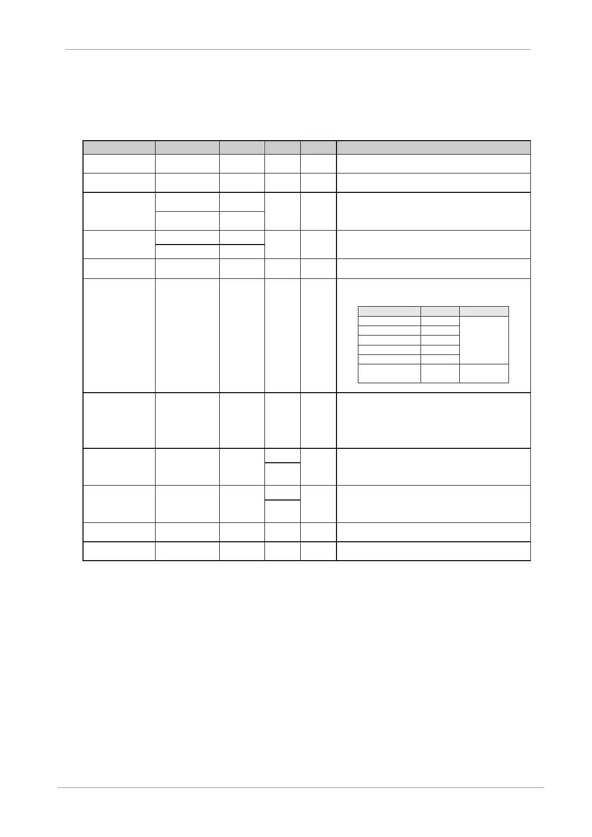
3. GENERAL INFORMATION SCREENS
On the display lower line it is possible to visualise the general programming information screens (G1 to
G16), which include all the information related to the motor and the equipment.
L1, L2 and L3 phase
current
Phase current. Shows the input three phases instantaneous
current
L1-L2, L2-L3, L1-L3
Line voltage
Line voltage. Show the input soft starter voltage between phases
Supply frequency / Motor phi cosine. Show the supply frequency
and the motor phi cosine.
Note: This screen can only be visualised after the soft starter has
completed the start.
Shows the power consumption and the axis torque.
Note: This screen can be only visualised when the motor is
running.
Shows the 1, 2 and 3 relay status.
Digital Inputs status
and Motor PTC
status
0 – Open
X – Closed
K – Correct
F – Fault
The first five digits refer to the digital input and the sixth one to the
PTC temperature probe input.
When the motor current is smaller than the overload value
introduced on screen [G3.2], the Overload Status is 1%. However,
when the current increases over the overload value, the Overload
Status factor increases, faster as the difference between values
increases. When the Overload Status factor reaches 100%, the
soft starter will “trip” due to F4.
When shown in mA the user has selected 0 or 1 on the [G6.8]
screen. When shown in V, the user has selected option 2 on the
[G6.8] screen. The following value will have BAR, ºC, m, % units
depending on the selection made on [G6.10] Screen.
This screen shows the analogue input 2 in V or mA, depending on
the configuration chosen on screen [G6.11] and the units the user
has configured on screen G6.13 and the scale selected on screen
[G6.12].
Show the output analogue 1 value, in real values and percentage
over the analogue output range.
Software y Hardware
revision
Shows the soft starter’s Software (S/W) and Hardware (H/W)
revision.

 Loading...