VS65 SERIES MV SOFT STARTER
G15.5 / Auto
reset fault 1
selection
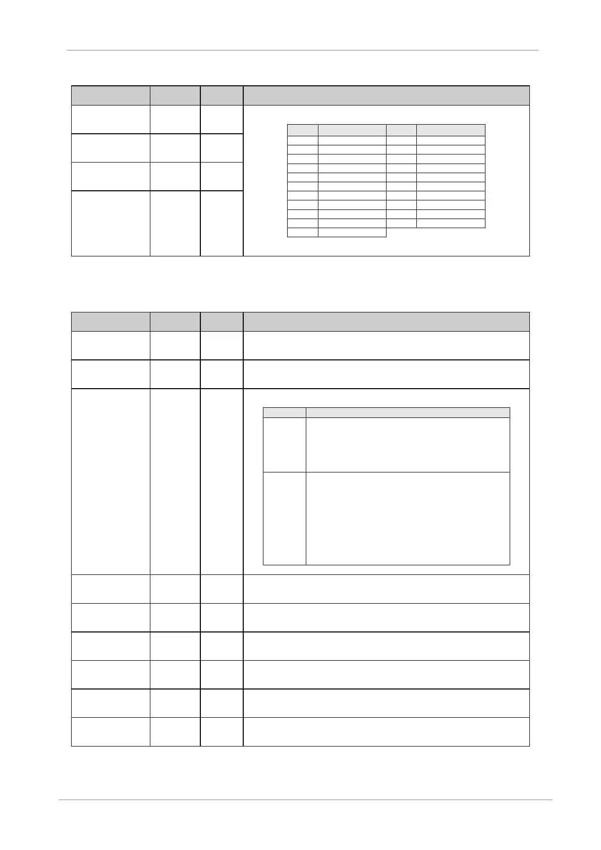
It selects fault no1 for the auto reset mode.
Note: Option 20 will automatically reset any of the above table faults.
G15.6 / Auto
reset fault 2
selection
G15.7 / Auto
reset fault 3
selection
G15.8 / Auto
reset fault 4
selection
4.13. Group 16 – G16: PUMP CONTROL
G16.1 /
Irrigation time
adjustment
Sets the time for the system to be irrigating.
VS65 irrigation timer can be reset [G16.2] (back to 0Hrs.) by decreasing [G16.1] to the same
value than [G16.2].
G16.2 /
Irrigation time
display
Displays the time the system has been irrigating.
Note: Read only screen.
G16.3 / Start
mode selection
Selects the start mode of the system.
Display unit: Enables the display unit for start stop control of the
VS65. This is the only way in which the VS65 can be started or
stopped. Digital inputs are preconfigured as follows:
Note: only used for the low voltage trial.
Wire: (Face Plate stop button is Reset only). Remaining digital
inputs are preconfigured as follows:
D INPUT 1 High Pressure switch connection (normally closed).
D INPUT 2 Low pressure switch connection (normally closed).
D INPUT 3 Flow switches connection (normally closed).
D INPUT 4 Deep well probe connection (normally closed).
D INPUT 5 is configured for remote two wire start/stop. This input
acts as a reset command on closing edge.
G16.4 / High
pressure
timeout
This is the time delay before the VS65 trips once the high pressure switch connection opens the
D INPUT 1.
Note: VS65 ramps down to stop.
G16.5 / Low
pressure
timeout
This is the time delay before the VS65 trips once the low pressure switch connection opens the
D INPUT 2.
Note: VS65 ramps down to stop.
G16.6 / Low
pressure start
bypass time
Sets the start bypass time, during which the VS65 starter ignores the Low Pressure input on D
INPUT 2.
G16.7 / No
Flow Start
Bypass time
Sets the time period for which the flow switch input is ignored following a start command on D
INPUT 3).
G16.8 / No
Flow Debounce
Delay
Sets the delay period before the starter responds to a no flow signal when in normal run
operation. (D INPUT 3).
Note VS65 ramps down to stop.
G16.9 / Deep
Well Probe
Delay
Sets the delay period before the starter stops after receiving a valid deep well probe signal. (D
INPUT 4).
Note: VS65 freewheel stop ramps.

 Loading...