MOVE ZR Installation & Owner’s Guide | 15
INSTALLING THE REALFEEL
®
FOOT PEDAL
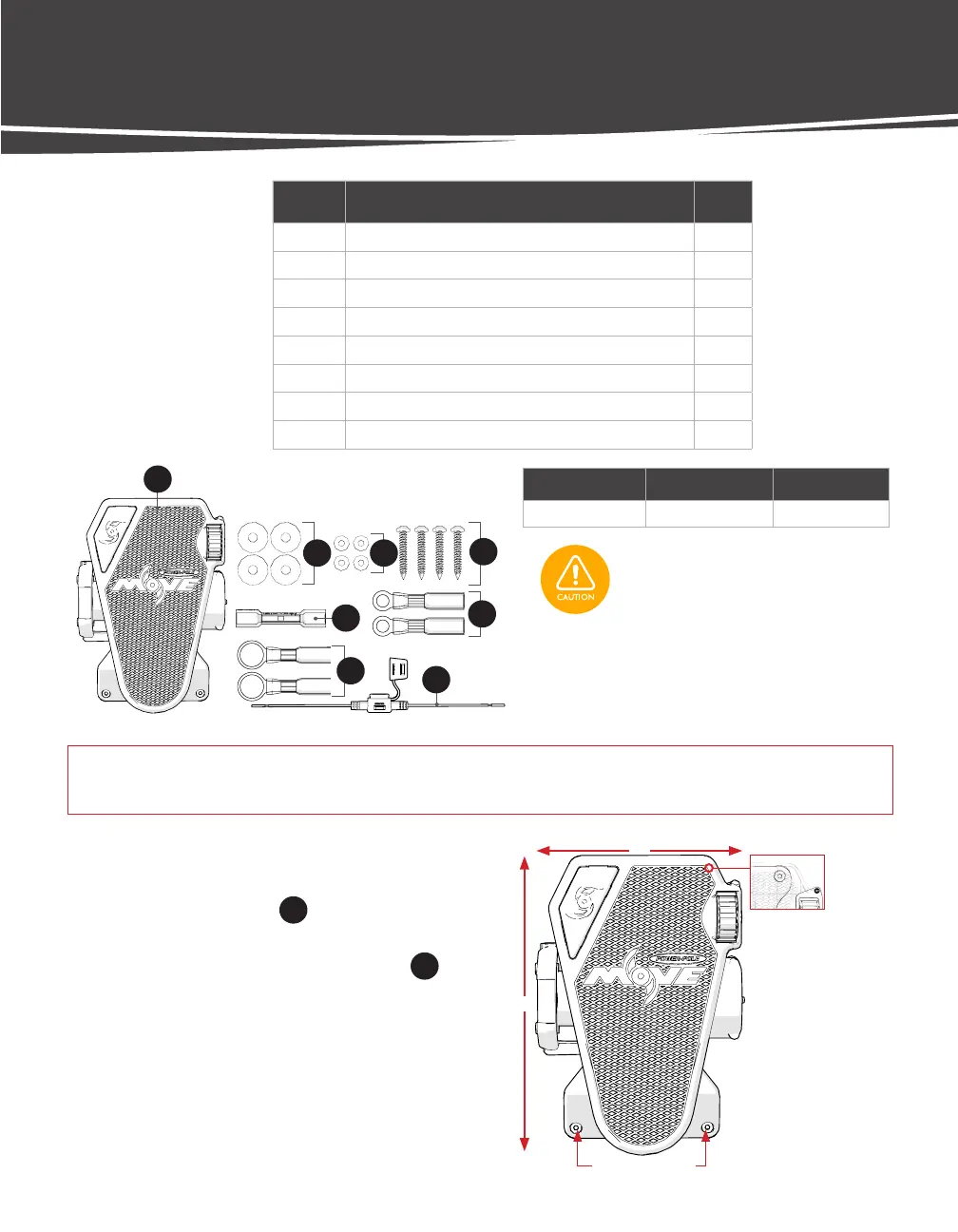
LABEL DESCRIPTION QTY.
27 Foot Pedal Assembly 1
28 1/4" Thick Rubber Bushing 4
29 Small Stainless Washer 4
30 #10 x 1 1/4" Panhead Sheet Metal Screw 4
31 Heat Shrink Butt Connector, 14-16 AWG 1
32 Heat Shrink Ring Terminal, 14-16 AWG #10 2
33 Heat Shrink Ring Terminal, 14-16 AWG, 3/8" 2
34 Fuse Holder, ATC, and ATO, 14 AWG, Red Leads 1
8"
11 3/4"
Mounting Holes
Mounting Holes
IMPORTANT! If installing to gel-coat, follow the drilling procedure in Appendix A (p. 41) to ensure you do not crack
or chip the gel-coat.
DRILL MOUNTING HOLES
STEP 1 Choose a flat surface with adequate space to
mount the Foot Pedal
27
.
STEP 2 Using the included mounting template, mark and
drill (4) pilot holes for Mounting Screws
30
using a 9/64" Drill Bit.
TOOLS:
• Fine-tip Marker
• Electric Drill
• 9/64" Drill Bit
• Phillips Head Bit
Dimensions Wire Length Wire Gage
8" x 11 3/4" ~5' 14 AWG
FOOT PEDAL HARDWARE
Check the area beneath where the Foot
Pedal will be mounted to ensure there
are no hoses, wires, lines, tanks, or other
sensitive components.
27
28 29
30
32
34
33
31
 Loading...