MOVE ZR Installation & Owner’s Guide | 17
INSTALLING THE INFO DISPLAY
PREFERRED INSTALLATION (Installing Wire Through Boat)
STEP 1 Using a #2 Phillips Head Screwdriver, install (2) Screws
15
and tighten until flush.
STEP 2 If running wire through boat surface, drill routing hole with a
7/32" Drill Bit.
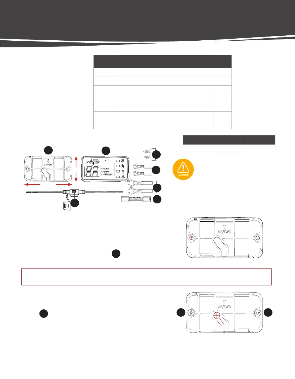
LABEL DESCRIPTION QTY.
13 Display Base 1
14 Move Info Display Assembly 1
15 Screw, Sheet Metal, Flat Head Phillips Drive 2
16 Heat Shrink Ring Terminal, 18-22 AWG, #10 2
17 Heat Shrink Ring Terminal, 18-22 AWG, 3/8" 2
18 Heat Shrink Butt Connector, 18-22 AWG 1
19 Fuse Holder, ATC, and ATO, 18 AWG, Red Leads 1
Dimensions Wire Length Wire Gauge
2" x 3 3/4" ~4 ft. 20 AWG
TOOLS:
• Fine-tip Marker
• Electric Drill
• 7/32" Drill Bit
• 7/64" Drill Bit
• Phillips Head Bit
3 3/4"
2"
DISPLAY HARDWARE
DRILL MOUNTING HOLES
STEP 1 Choose a flat surface with adequate space to mount
the Info Display.
STEP 2 Lay the mounting template in the desired mounting location and drill
pilot holes for Mounting Screws
15
using a 7/64" drill bit.
Mounting Holes
IMPORTANT! If installing to gel-coat, follow the drilling procedure in Appendix A (p. 41) to ensure you do not
crack or chip the gel-coat.
Hole for Wire
Check the area beneath where the
Display will be mounted to ensure there
are no hoses, wires, lines, tanks, or other
sensitive components.
13
15
14
16
19
17
18
15 15
 Loading...