37
Note: if you wish simply to switch servos or valves on or off, you must always enter a time
difference in the sequence, as the door sequencer needs a small amount of time to carry out
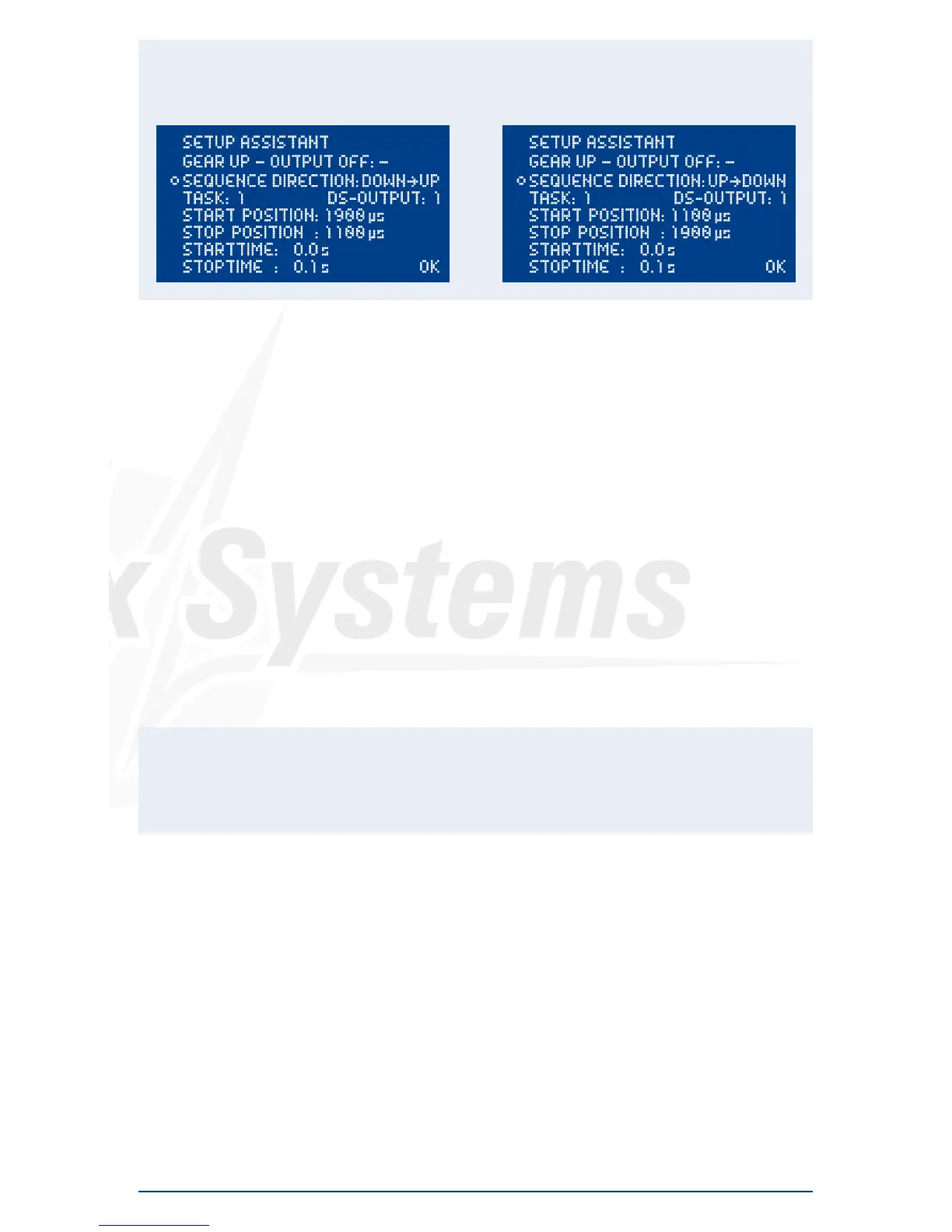
its calculations. The following is an example for a retract valve:
The time lag of 0.1 s is sufficient, and is virtually unnoticeable in practice.
Important: the first START POSITION at UP » DOWN must always coincide exactly with the last
STOP POSITION of DOWN » UP. This simply means that the last task must cause the servo to return
to its starting value, regardless of any individual intermediate steps you create! If the wheel door
servos carry out unusual or unexpected movements when you try out the programmed sequence,
please check your tasks!
9. CHANNEL LOCK WHEN UNDERCARRIAGE IS RETRACTED
The PowerBox Royal SRS’s door sequencer also features one last unique function: it is now pos-
sible to switch a channel off when the undercarriage is retracted. The purpose of this feature is to
prevent the retracted nosewheel moving inside the fuselage when the pilot gives a rudder com-
mand, as this may cause the mechanical system to jam. The function can be found under GEAR
UP - OUTPUT OFF in the Door Sequencer menu. Simply use the SensorSwitch to select the output
which you wish to disable when the undercarriage is retracted. Select the output, and confirm your
choice with the SET button; at the same time the system stores the position of the nosewheel servo
at which it is to remain.
Caution: This function is extremely useful, but it also creates a danger: if you accidentally
include a control channel (e.g. elevator) in your programming, the control channel will then be
switched off when you retract the undercarriage after the model takes off. This will usually
result in loss of the model!
10. POWERBUS
The PowerBUS is the key to a completely new servo wiring arrangement. The PowerBUS consists of
three wires which supply current and signal to the servos connected to the unit. At first glance this
is nothing unusual, but the big difference lies in the signal wire. When conventional servo signals
are transferred, the signal wire always carries the information for one individual servo only - this is a
PWM (Pulse Width Modulated) signal. In a servo bus system the positional information for multiple
servos is transferred in digital form. The information for individual servos carries address data, and
since each servo is assigned its own individual address, it can read out “its” information from the
data stream, and convert it into a movement of the control surface.
The advantage is perfectly obvious: all you need is one three-core lead in order to supply the essen-
tial information to several servos. The wiring is much simpler, and there is also a significant weight
reduction.
 Loading...