5
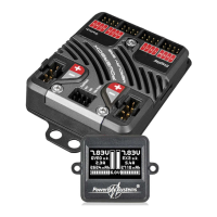
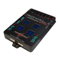
1. LAYOUT, CONNECTIONS
PowerBUS outputs
Battery sockets
RX1 and RX2 inputs
for Futaba, HoTT, M-Link, Jeti
Sat1 - Sat4 inputs for
Spektrum satellites
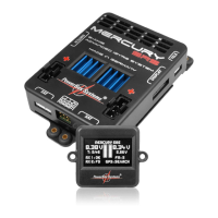
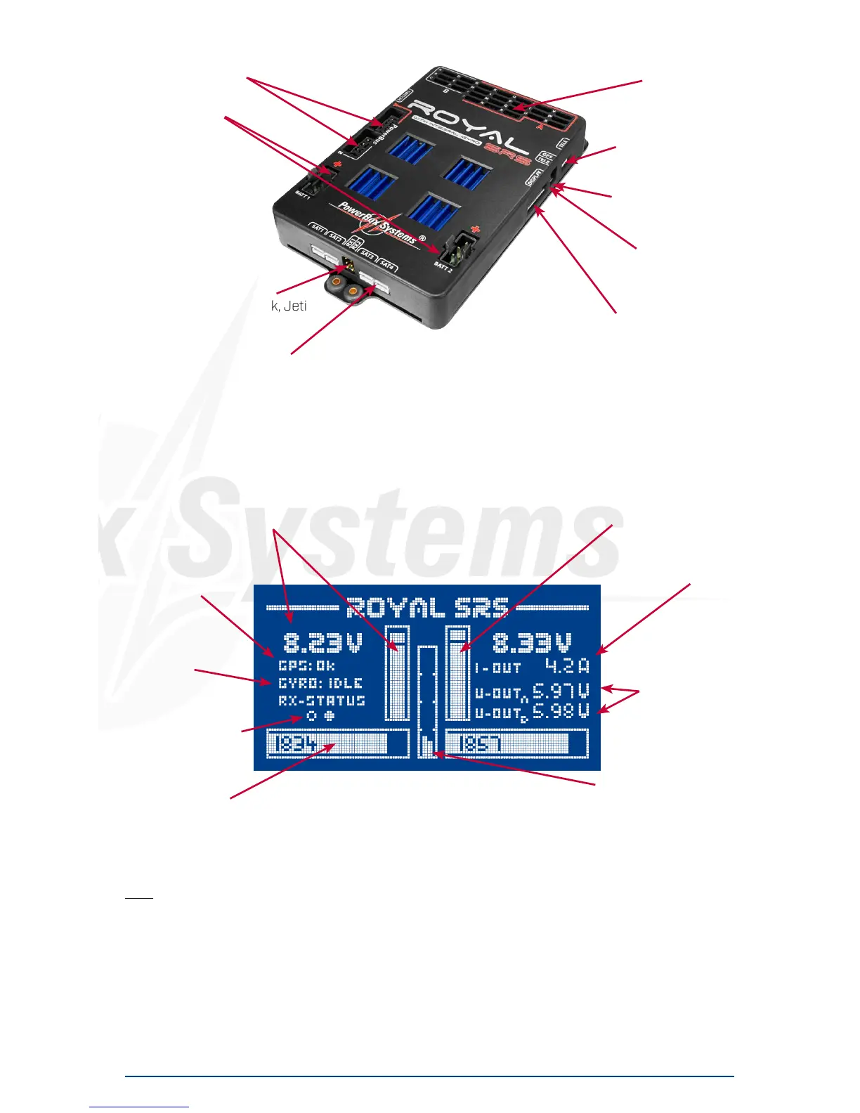
2. MAIN SCREEN, DATA LOGGER
Battery voltage display
GPS status
Gyro sensor status
Receiver status
Battery capacity
Key:
- Battery voltage indicator: Shows the exact battery voltage for both batteries, digitally and as bar
graph
- GPS status: If no GPS is connected here, the screen shows three lines. If switched on with GPS
connected, “SEARCH” is displayed while the system searches for GPS satellites. “OK” must be
displayed here before each flight.
- Gyro sensor status: Information display only. After a “Zero Gyro” the screen should display “IDLE”
at this point; an occasional “ACT” for ‘active’ is normal.
- Receiver status: This item shows which receivers are delivering a signal. Brief flickering of these
points is normal, provided that the receiver “Antenna fades“ counter displays normal values.
servo sockets
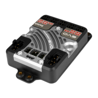
Spektrum TM1000
socket
GPS Sensor socket
Telemetry/USB
adapter socket
LCD screen socket
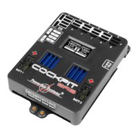
Min. value indicator
Total current output,
digital
Output voltage
Range A and B
Current output, Batt 1
and Batt 2, bar graph
 Loading...