Scroll Enclosure Air Compressor 15-60 HP
Operating & Maintenance Manual
Powerex • 150 Production Drive • Harrison, OH 45030 • USA
P 1.888.769.7979 • F 513.367.3125 • www.powerexinc.com
IN596202AV • 21 February 2023
Page 14 of 32
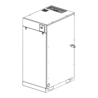
Alarm Signals
FIgure 14
The PLC control for the scroll enclosure compressor
will display the ALARM screen and activate the GENERAL
FAULT indicator on the alarm screen display if either of
the two conditions occurs:
1. High temperature at the sensor located at the after
cooler inlet. Each compressor module has its own
sensor. A high temperature condition will result
in the power to that motor being shut o. The
GENERAL FAULT alarm display will stay on and the
circuit will stay o even after the sensor cools, and
can only be restored when the alarm is cleared
by a user. If a high temperature condition occurs,
the reason should be determined and corrected
before restarting the circuit as unrepairable
damage to the scroll pump may result from
operation with repeated high temperature alarms.
2. Motor Overload, if the current to the motor
exceeds the setting of the adjustable motor
protector, the contactor associated with that
motor is de-energized, and that motor will not
run. The alarm display and condition is maintained
until the alarm is cleared and the motor protector
reset. The circuit will be restarted as needed. If a
motor overload occurs, the root cause should be
determined and corrected or motor damage may
result.
The user can activate the acknowledge function
(button labeled ACKN) to allow the display to go back to
SYSTEM STATUS or any other screen. Touch the VIEW
button to advance to a screen showing which pump-
motor assembly is in fault and for what reason. The
fault will display and the aected pump-motor will be
disabled until the RESET button is pushed.
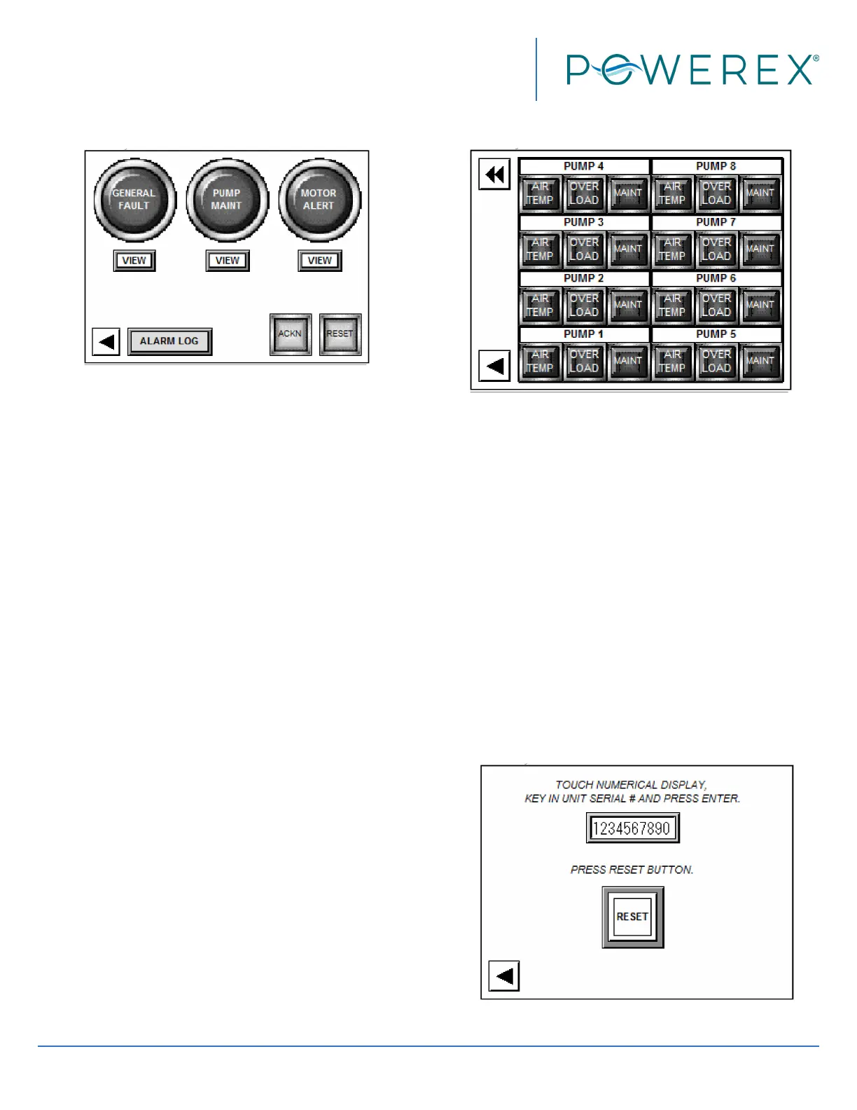
Figure 15
The PUMP MAINT indicator will activate when the
running hours of any pump accumulates to a required
maintenance interval. The system is designed for
multiple pumps to accu mulate hours evenly and for
maintenance intervals to be ap proached simultaneously.
To prevent nuisance PUMP MAINT indications, all
applicable maintenance counters should be reset after
the required maintenance actions are performed. Use
ACKN to allow the STATUS screen or other screens to
be displayed. Touch the VIEW button to advance to
the next screen. Consult the maintenance schedule on
page 15 and scroll air compressor manual for details of
what maintenance needs to be performed. To reset the
PUMP MAINT indicator for an individual pump, open the
PUMP INFO screen for that pump, hit the RESET button
and use the keypad display to enter the authorization
code when prompted.
Figure 16
 Loading...