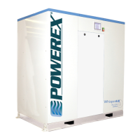
Scroll Enclosure Air Compressor 15-60 HP
Operating & Maintenance Manual
Powerex • 150 Production Drive • Harrison, OH 45030 • USA
P 1.888.769.7979 • F 513.367.3125 • www.powerexinc.com
IN596202AV • 21 February 2023
Page 7 of 32
3. Avoid connecting the safety valve with any tubing
or piping.
4. Manually operate the safety valve every six months
to avoid sticking or freezing.
Check Valves
Do not install a check valve between the compressor and
the air receiver or facility piping. If a check valve is installed,
the compressor pressure sensor will see rapid pressure
drops and cause short cycling of the motors and other
control problems.
Isolation Valves
An isolation valve should be installed between
the compressor and the air receiver to facilitate
maintenance. Make sure the valve is open when
operating the compressor. A second isolation valve
should be installed between the air receiver and the
facility piping.
Intake Air Connections
Powerex 7.5 and 10 HP Scroll enclosed models
normally have an intake lter assembled to each
compressor pump. These lters are located internal
to the sound mitigating compartment to provide
maximum protection for the pump and reduce noise
near the enclosed compressor system.
For models supplied with remote intake capability,
such as those used in Medical Air systems and other
special applications the pump intakes are routed
together and an externally mounted air lter assembly
is installed. This lter is provided with an isolation
valve so that if the unit is removed from service the
branch connection to the main intake header can be
closed. NOTICE operating the compressor unit with
the isolation valve closed will result in catastrophic
damage to the pumps. Powerex provides the valves
with the handle removed and stored in the system
control enclosure. We suggest utilization of this handle
be controlled to prevent accidental operation with the
valve closed. Multi-stack models such as the SEQ, SEP,
and SEH series will have a lter and valve for each stack.
Unit Vibration Isolation
Each pump motor assembly in the Powerex unit has
isolation mounting between its support rails and the
system frame. Additional isolation is not required, but
is allowable if desired. Powerex can supply cork rubber
composite mounting pads to use under the corners of
the base platforms if desired. Contact customer service
lines are covered. Before putting the unit into service,
nd and repair all leaks in the piping, ttings and
connections.
Select the size of the air receiver so that the combined
volume of
Dierenal* Duplex Triplex Quad Penta Hex
Min. 120 120 200 200 240
Standard 120 120 120 200 240
Max. 120 120 120 120 200
*Pressure seng selected on control panel
Table 2
the air receiver and facility piping results in a long
enough cycle time to keep any individual motor from
starting more than once every 3.43 minutes. Selecting
the widest possible spread between high and low system
set point pressure along with the largest dierential for
each pump interval will reduce the starting frequency.
The table below shows the recommended tank size
in gallons per model. Some conditions of air usage may
require additional volume.
1. Make sure the piping is lined up without being
strained or twisted when assembling the piping to
the scroll enclosure.
2. Appropriate expansion loops or bends should
be installed at the compressor to avoid stresses
caused by changes in hot and cold conditions.
3. Piping supports should be anchored separately
from the compressor to reduce noise and
vibration.
4. Never use any piping smaller than the compressor
outlet connection.
5. Use exible hose to connect the outlet of the
compressor to the piping so that the vibration of
the compressor does not transfer to the piping.
Safety Valves
Safety Valves must be installed on every receiver. The
ow capacity of a safety valve should be equal to or
greater than the capacity of the compressor.
1. The pressure setting of the safety valve must not
be greater than the maximum working pressure
of the air receiver.
2. Safety valves should be placed ahead of any
possible blockage point in the system, i.e. shuto
valve.

 Loading...