Scroll Enclosure Air Compressor 15-60 HP
Operating & Maintenance Manual
Powerex • 150 Production Drive • Harrison, OH 45030 • USA
P 1.888.769.7979 • F 513.367.3125 • www.powerexinc.com
IN596202AV • 21 February 2023
Page 16 of 32
Maintenance
The 7.5 and 10 HP Scroll Enclosed units are
constructed with the Powerex patent pending Service
Slide feature. Each pump motor baseplate is mounted
to a set of rails that are separated from the system frame
by anti-vibration pads. The baseplate is constructed so
that its mounting brackets may be loosened slightly
and the assembly moved on the rails to improve access
for regular maintenance and major service or repair.
The baseplate assemblies may be moved outwards
from the frame set on the motor side. For the top bay
in each stack, the instrument panel will need to be
removed and set aside to provide clearance. IN some
cases it may be more convenient to simply remove the
roof panel to provide access.
When performing tip seal and bearing grease
maintenance actions, the pumps can be accessed from
the left and right side panels. Spacing of the pump bays
is sucient to allow use of the Powerex grease gun , but
sliding the set out can be more convenient or a ex hose
can be used with the grease gun to facilitate greasing
from the side where tip seal access is obtained.
If the Service Slide feature is utilized, it may be
benecial to leave the pump end, belt side, corner
bracket to rail, screw just loose enough to slide; rather
than clamping it tight. No operational issues will arise
and it will facilitate future use of the slide feature.
Maintenance for Mul-stack systems follows. Single stack
systems have similar features, but do not have circuit breakers
for le-right stack isolaon.
Locking Out Potential to Perform Maintenance
Procedures
The enclosure is equipped with the components to
mechanically and electrically lock out both stacks of
pump/motor assemblies. Proper OSHA lockout/tagout
procedures should be abided by at all times. Electric
potential to each motor can be locked out using the
lockable motor protectors. (See Figure 5) Electric
potential to the ventilation fans and temperature
switches can be locked out using the 4 circuit breakers
provided on the control panel. (See Figure 6) Circuit
breakers #1 and #3 are associated with the left bank
of compressors while #2 and #4 are associated with
the right bank. Mechanical potential can be locked
out using the lockable ball valves located behind the
control panel and are accessible by removing the back
center intake panel. (See Figure 7) After closing either
ball valve, bleed the remaining line pressure by pulling
the provided safety relief’s ring to remove all potential
within a bank of compressors. Some models do not
include locking ball valves and require locking covers
for secure isolation.
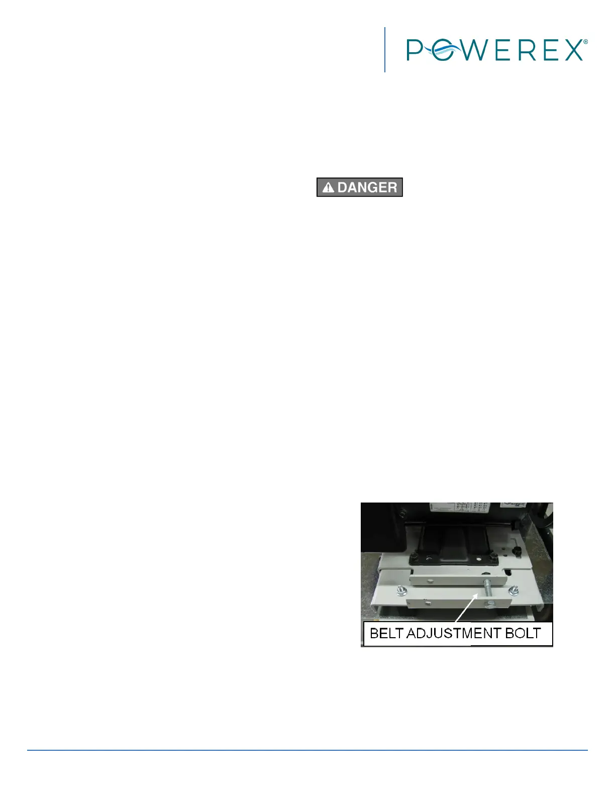
Adjusting Belt Tension
Moving Parts! Lock out power before
servicing unit!
After the rst 200 to 500 running hours or at any time
chirping is heard on start up, check the belt tension.
If tension is below 25 pounds on any belt, increase
the center distance using the motor slide base so that
belt tension is 45 to 50 pounds. The motor slide base
details are shown below. If installing new belts see the
procedure below:
New Belt Installation Procedure
1. Loosen the two slide bolts near the motor pulley
and the two slide bolts on the front edge of the
base. Keep enough torque on them to take up
any slack between the slider and the main base,
but enough slack to allow the slider to move.
2. Tighten the belt adjustment bolt using a torque
wrench to 45 inch pounds. This will bring the belts
to the proper tension.
3. Tighten the slider bolts, the two on the front edge
of the base, then the two slider bolts closest to
the motor pulley so the belt tension is 45 to 50
pounds.
Figure 20
 Loading...