Scroll Enclosure Air Compressor 15-60 HP
Operating & Maintenance Manual
Powerex • 150 Production Drive • Harrison, OH 45030 • USA
P 1.888.769.7979 • F 513.367.3125 • www.powerexinc.com
IN596202AV • 21 February 2023
Page 5 of 32
Installation Site
1. The scroll compressor must be located in a clean,
well lit and well ventilated area. A contaminated
area can clog the intake lter and / or intake metal
mesh.
2. The area should be free of excessive dust, toxic
or ammable gases, moisture and direct sunlight.
3. Never install the compressor where the ambient
temperature is higher than 104°F or where
humidity is high. High humidity will cause electrical
short circuit and rusting of components.
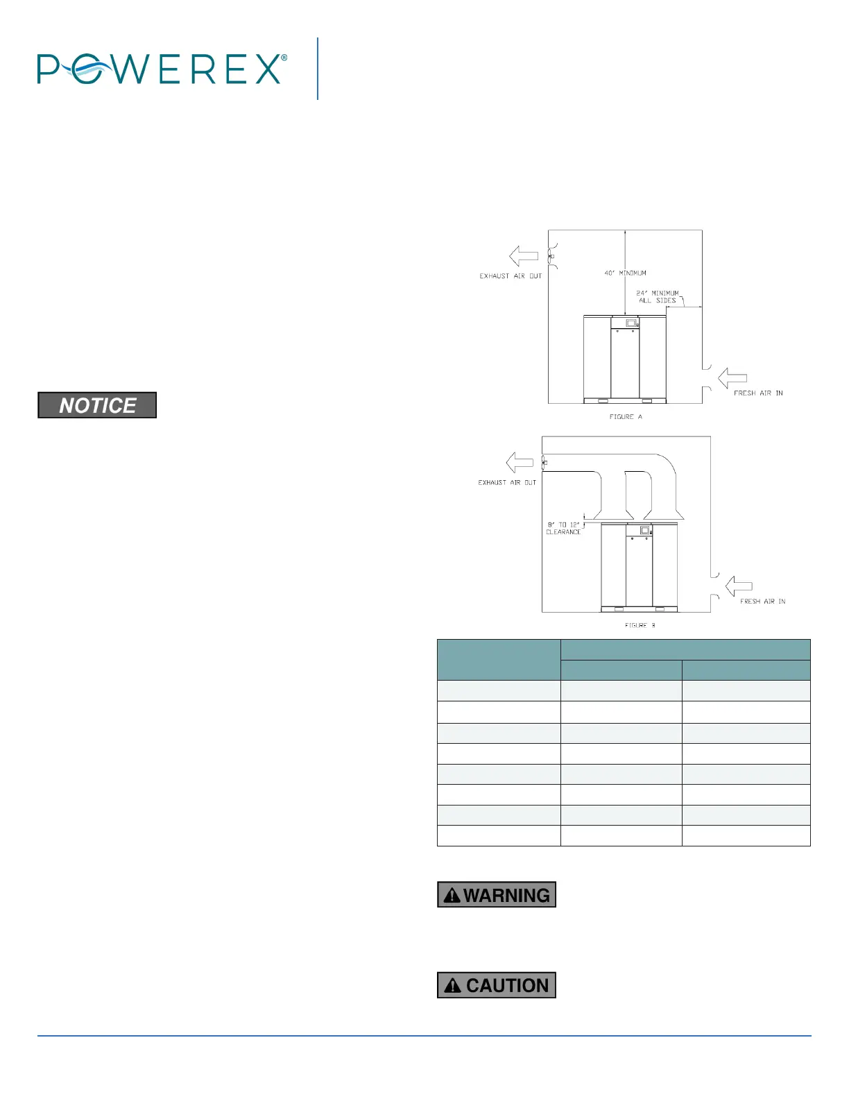
4. Clearance must allow for safe, eective inspection
and maintenance.
A minimum of 24 inches of clearance
for sides, 40 inch clearance from the top is required.
Consult OSHA and NEC for requirements on clearance
for electrical access. 36 inches or more may be required.
5. If necessary, use metal shims or leveling pads to
level the compressor. Never use wood to shim the
compressor.
Ventilation
1. If the scroll compressor is located in a totally
enclosed room, an exhaust fan with access to
outside air make up air must be installed.
2. Never restrict the cooling fan exhaust air or the
intake cooling air.
3. Vent the exhaust air outside to prevent the
compressor from operating at high temperatures
and shutting down.
4. Never locate the compressor where hot exhaust
air from other heat generating units may be pulled
into the unit.
Suggested Ventilation System
The temperature rise in the room must be kept
to a maximum of 10 F. The BTU capacity of the vent
system should be sized for the full operating HP rating
of the compressor. Suggested fan capacity at 0 static
pressure is shown below. If static pressure is higher,
the fan capacity should be increased.
An exhaust duct may be installed to capture the warm
air exiting the compressor enclosure. The opening of
the exhaust duct should be about 6 inches larger on
each side than the vent openings on the compressor
top panel. The duct should not obstruct removal of the
top panel for service. Leave between 8 and 12 inches of
clearance. The CFM capacity of the exhaust fan should
be increased to compensate for duct ow losses.
Increase CFM if incoming air is above 85°F.
Total HP
Exhaust CFM Required
Figure A Figure B
15 5000 1700
20 6700 2200
22.5 7600 2500
30 10100 3400
40 13500 4500
45 15100 5000
50 16800 5600
60 20200 6700
Wiring
All wiring and electrical connections
must be performed by a qualied electrician.
Installations must be in accordance with local and
national codes.
Overheating, short circuiting and re
damage will result from inadequate wiring.
 Loading...