Scroll Enclosure Air Compressor 15-60 HP
Operating & Maintenance Manual
Powerex • 150 Production Drive • Harrison, OH 45030 • USA
P 1.888.769.7979 • F 513.367.3125 • www.powerexinc.com
IN596202AV • 21 February 2023
Page 8 of 32
if necessary. Some systems may be provided with the
isolation pads.
Condensation and Condensation Separators
The Powerex 7.5 and 10 HP Scroll Enclosed
compressor units include after coolers that will
generate condensation in the compressed air outlet
lines. Some models are shipped with condensate traps
for eld installation external to the enclosure and
systems will typically have condensate traps installed by
Powerex. Locate the condensate traps where they can
be conveniently accessed for maintenance. When an
isolation valve is used for a compressor unit, it may be
benecial to locate the trap on the compressor side so
the trap can be isolated with the unit for maintenance
and service.
Do not install check valves between
the compressor unit and the system air receiver. The
compressor pressure sensor must be in full connection
with the air receiver for the controls to operate properly.
Installation of a check valve will usually result in short
cycling the compressors and may damage the motors
and controls and reduce the compressor service life.
Do not modify the internal ow path
of the compressor unit. Do not modify the access
covers or latches. Improper modications may result
in risk of bursting, risk of injury and risk of equipment
damage. Do not operate the system with access covers
removed, as this will result in the risk of injury due to
access to internal moving or hot parts.
Do not modify the electric controls
or add any auxiliary loads to the electric system that
are not part of the original Powerex design. The main
power and control power circuits may be damaged by
unauthorized loads or modications resulting in a risk
of death or injury or equipment damage.
Control Panel – Display & Input
The Powerex scroll enclosure air compressor has a
power control switch and a touch screen or HMI panel
on the front to allow operation and monitoring of the
unit. See Controls section for details on operating the
unit using the touch screen.
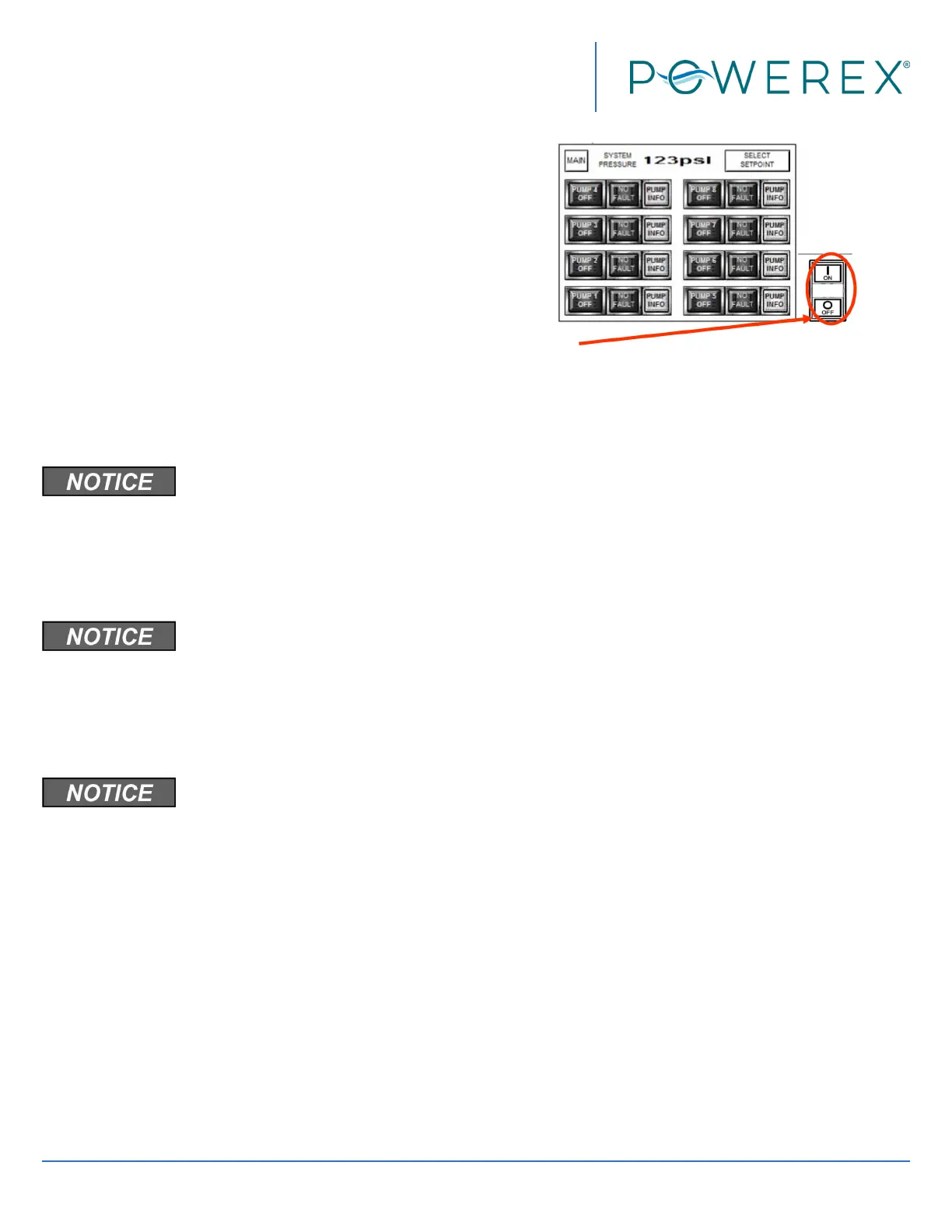
The switch beside the screen controls power to the
motor starters. When the system is energized the HMI
screen will be lit and the control screen is active, but
the motors will not run until the ON button is pushed.
When ON is pushed, the center section of the switch
will illuminate, enabling the PLC control of the system,
and will remain lit until the OFF button is pushed. The
OFF button on the switch may be used to stop the
compressors at any time. The switch does not turn o
power to the panel so be sure to lock out the power
source before opening the panel for service.
NOTE: The “Jog” function on the screen overrides the
ON switch. The motors will operate if the Jog button
is continually depressed. To reach “JOG” press the
SYSTEM STATUS button, then press PUMP INFO for the
pump module you want to jog.
The PUMP INFO screen is shown below. Press the >
arrow button to jog pumps.
 Loading...