32
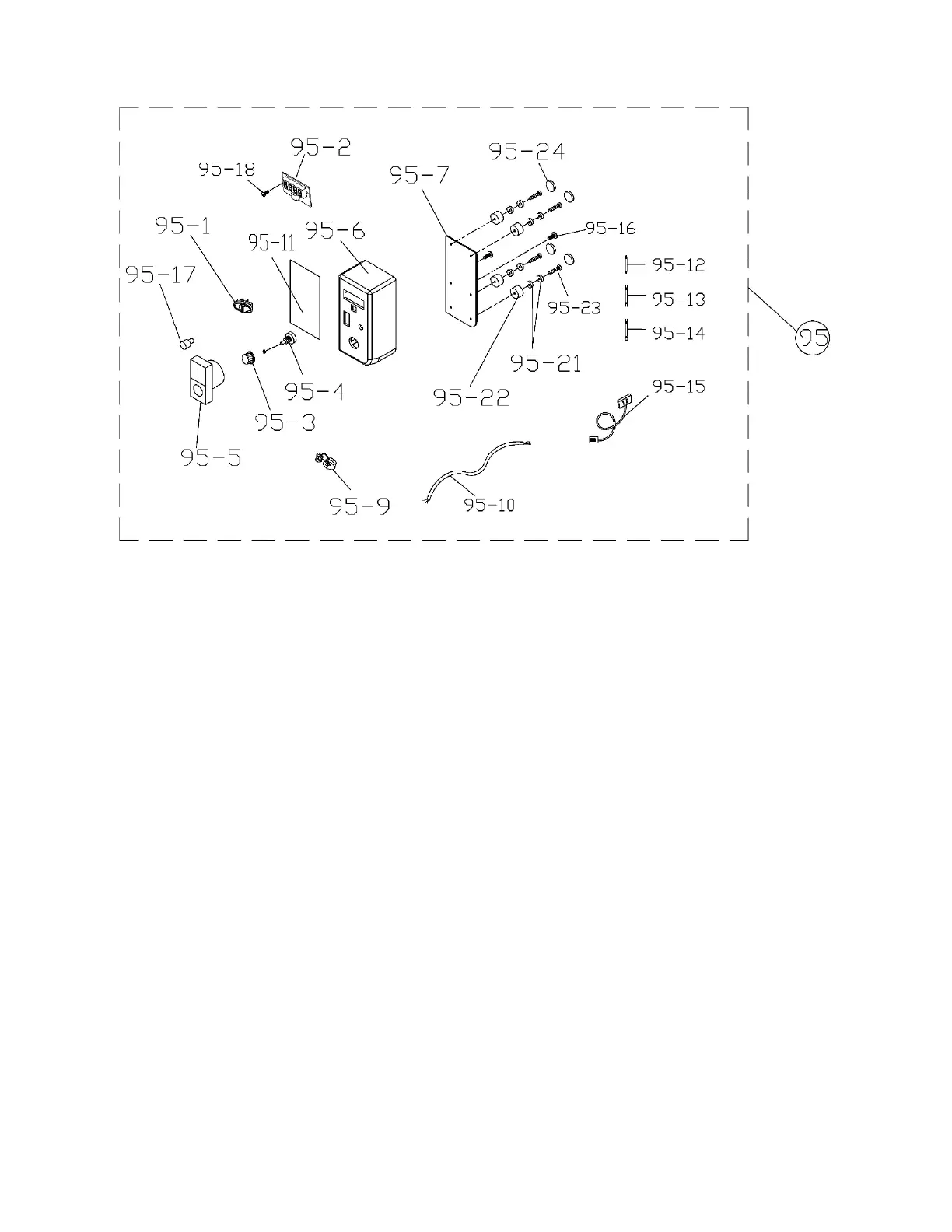
15.3.1 PM2014 Remote Control Box Assembly – Exploded View
15.3.2 PM2014 Remote Control Box Assembly – Parts List
Index No. Part No. Description Size Qty
95 .............. PM2014-195 .............. Remote Control Box Assembly (includes # 95-1 thru 95-24) ......................... 1
95-1 ........... 4224B-148 ................. Switch Fwd. /Rev ..................................................... ...................................... 1
95-2 ........... 3520C-1412 .............. Digital Readout Display ........................................... ...................................... 1
95-3 ........... 6430047 .................... Knob ........................................................................ ...................................... 1
95-4 ........... 6295915 .................... Control Pot Assembly .............................................. ...................................... 1
95-5 ........... 3520C-1415 .............. Control Switch ......................................................... ...................................... 1
95-6 ........... 3520C-1416 .............. Remote Control Box (includes #41-11) ................... ...................................... 1
95-7 ........... 3520C-1417 .............. Control Box Back Plate ............................................ ...................................... 1
95-9 ........... SR-6P3 ...................... Strain Relief ............................................................. SR-6P3 ......................... 1
95-10 ......... 3520C-14110 ............ Signal Cable (Remote switch box to Inverter) ......... ...................................... 1
95-11 ......... 3520C-14111 ............ Control Box Label .................................................... ...................................... 1
95-12 ......... 3520C-14112 ............ Wire (Control Pot to control switch, White) .............. ...................................... 2
95-13 ......... 3520C-14113 ............ Wire 2 (for control switch, Brown) ............................ ...................................... 1
95-14 ......... 3520C-14114 ............ Wire 3 (control switch to Fwd. /Rev Switch, yellow) ...................................... 1
95-15 ......... 3520C-14115 ............ Signal Cable ............................................................ ...................................... 1
95-16 ......... F010944 .................... Flat Head Socket Screw BO .................................... M3-0.5x20 ..................... 2
95-17 ......... 3520C-14117 ............ LED Light ................................................................. ...................................... 1
95-18 ......... F010987 .................... Flat Head Socket Screw BO .................................... M3-0.5x10 ..................... 2
95-21 ......... 3520C-148 ................ Magnet ..................................................................... ...................................... 8
95-22 ......... PM2014-19522 .......... Rubber Pad ............................................................. ...................................... 4
95-23 ......... TS-2283302 .............. Phillips Pan Hd Machine Screw ............................... M3x30 ........................... 4
95-24 ......... PM2014-19524 .......... Mat ........................................................................... ...................................... 4
 Loading...