18
DigiMod 500 1000 1500 2000HV 1000NPS | SERVICE MANUAL
INDEX
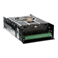
+15Vdc -15Vdc
By means of the DIGIMOD AMP AUX VOLTAGE CABLE, connect a
DC power supply and set the output voltage to ± 15Vdc. (Fig. 13)
(Fig. 13)
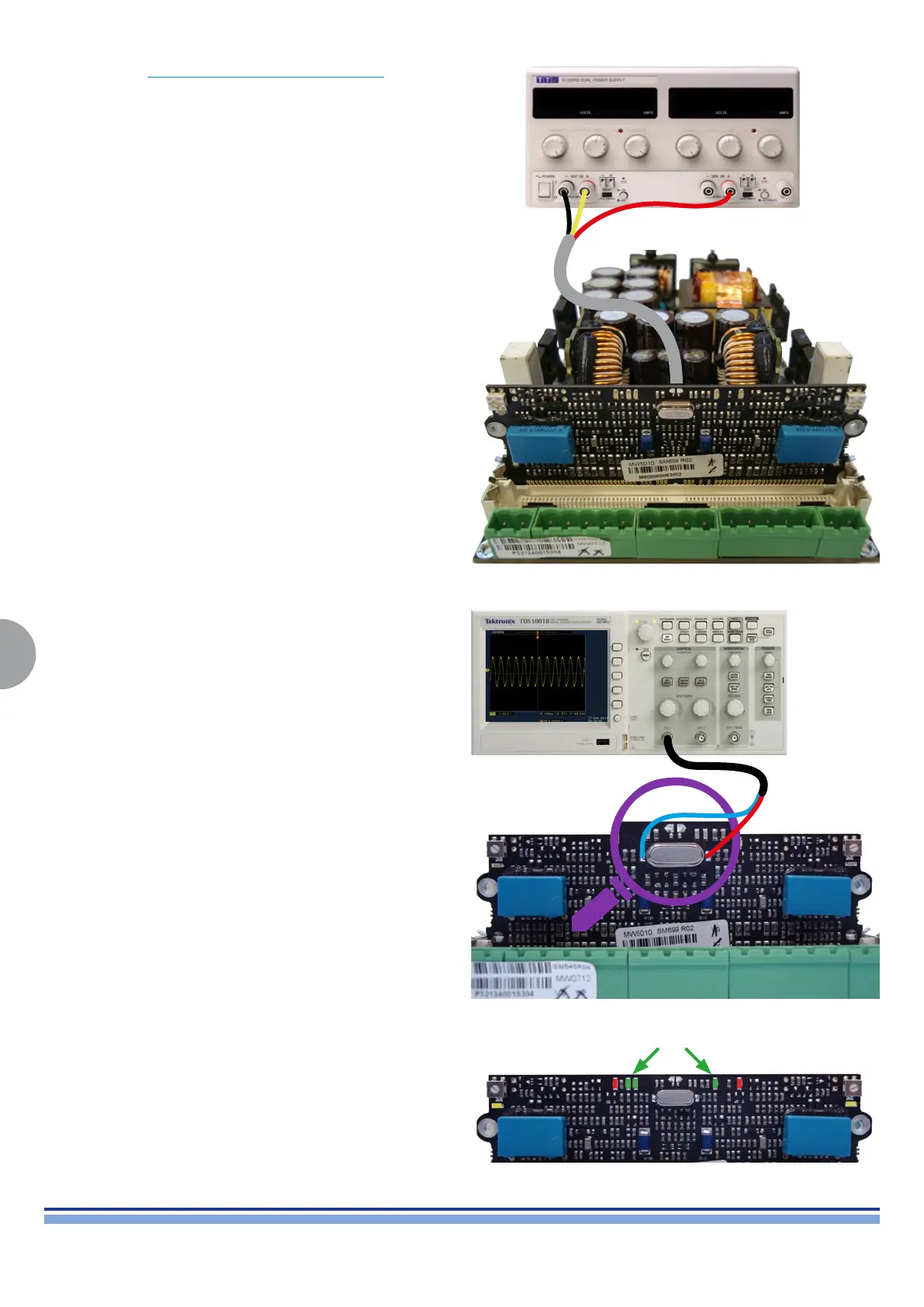
(Fig. 14)
Check the Control board by measuring its oscillator’s clock signal,
it should be 12MHz. (Fig. 14)
In this conguration, all 3 green LEDs should be on, whilst both
yellow ones should be OFF. (Fig. 15)
Any other LED conguration is a sign oaf a CNTRL Board fault, in
this case replace the CNTRL Board.
(Fig. 15)

 Loading...