INDEX
17
M SERIES | SERVICE MANUAL
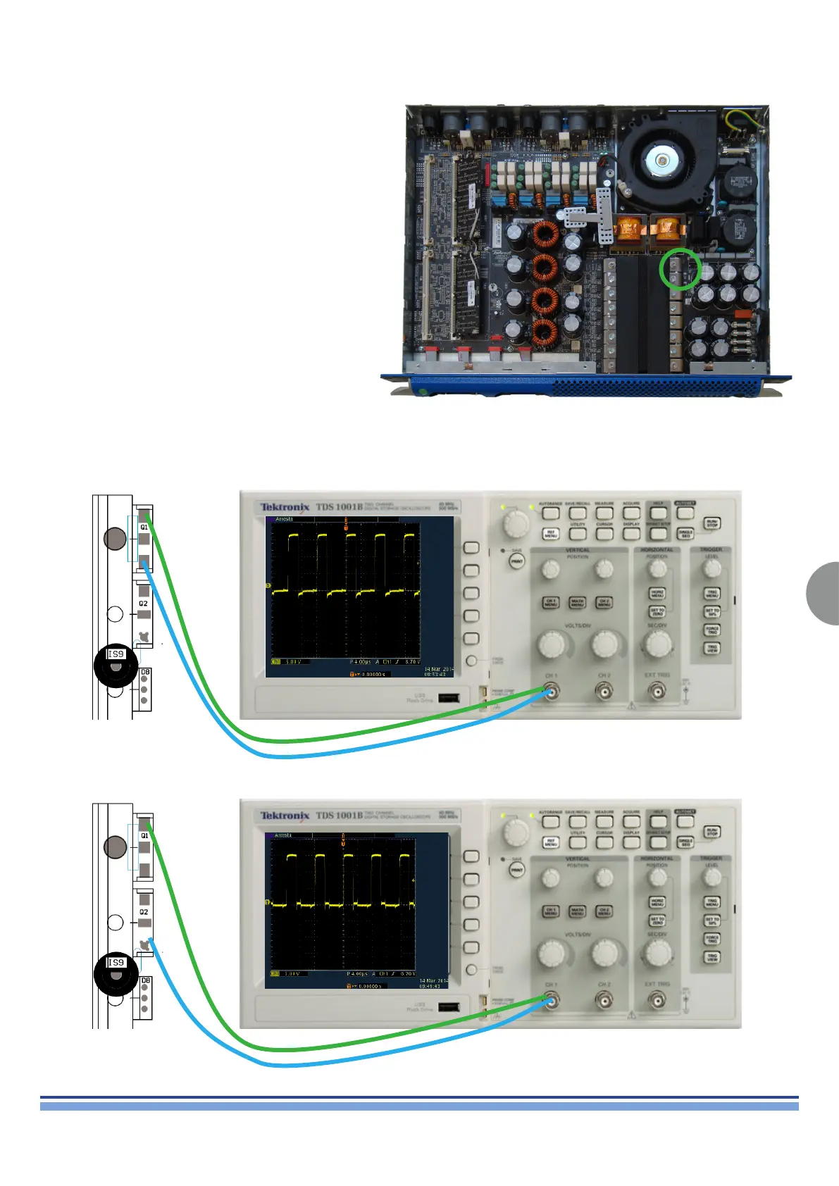
Check the Q1, Q2 gates highlighted on (Fig. 36) by means
of an oscilloscope.
(Fig. 36)
The following pictures (Fig. 37, 38) portray a more detailed
view of the setup and the waves that must appear on the
oscilloscope in order to validate the test.
(Fig. 37)
(Fig. 37)
5.00V - 4.00μS
5.00V - 4.00μS
 Loading...


