▶
11
M Series User Guide
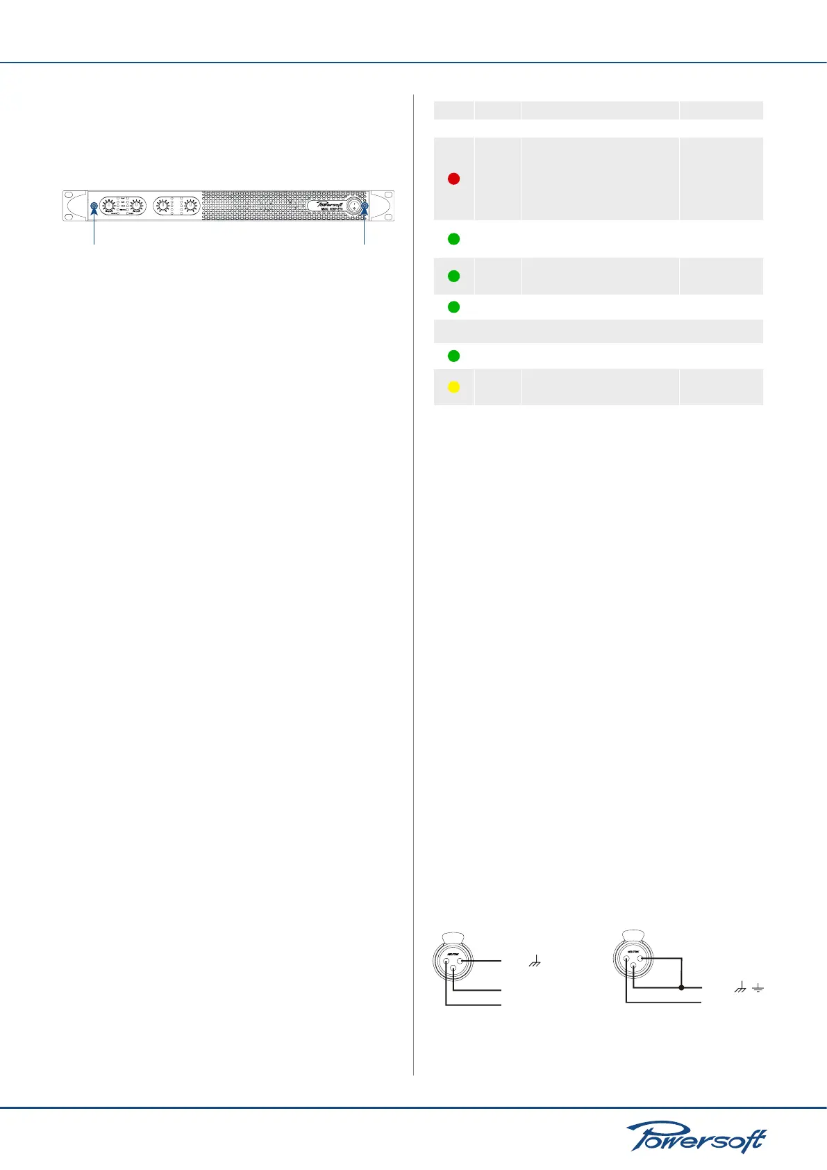
1. remove the two screws highlighted in FIGURE 11 with a
Philips screwdriver. The panel will easily separate from the
amplier exposing the sponge-like air lters.
To reposition the front blue colored panel:
TEMP
READY
SIGNAL
-18dB
6dB
CLIP
FIGURE 11: Screws to be removed in order to access the air lters
behind the front panel
1. before replacing the front panel, reposition the air lter on
the chassis by placing it on its designated area
2. reposition and tighten the two frontal screws.
5.3 Front Panel Adjustments
The front panel of all M Series ampliers has one stepped attenuation
knob for each channel. Turning the knob counterclockwise, the
user can select the amplier’s gain value in steps corresponding
to the following values: -∞, 4, 14, 18, 20, 22, 24, 26, 28, 30, 32 dB.
5.4 Front Panel Monitoring
The M Series front panel provides important information on the
state of the amplier. It is important to know and understand the
meaning of every front panel indicator LED in order to have crucial
information on what’s going on and what could be going badly
with the amplier.
There are two sets of LEDs on the M Series front panel. There are
Channel indicators and Status Indicator LEDs. Channel indicators:
each channel has its own column set of 4 LEDs. The top LED
is red, and the following three are green. Status indicators: each
channel pair has one set of two green status indicator LEDs.
The function of both families of LEDs is summarized in the
following chart:
LED Color Solid color Front panel label
Channel indicators
Red
Channel output level has reached
clipping limits
OR
Short circuit protection has been
engaged
CLIP
Green
Channel output level is above -6 dB of
max output level
-6 dB
Green
Channel output level is above -18 dB
of max output level
-18 dB
Green Signal is present at amplier output SIGNAL
Status indicators
Green Channel is ready READY
Yellow
Output power is being reduced due
to heat sink temperature rising above
75° C
1
TEMP
1
Should the temperature increase beyond 85° C, the LED will stay on and the channel
will be muted. The amplier will resume normal functioning and the LED will turn off
automatically when the temperature falls below 75° C.
FIGURE 12: Front panel LEDs chart
5.5 Rear Panel
The rear panel of the M Series with optional DSP has a 4-green-
LED column per channel pair. The LED lights to indicate which
preset is active for that specic channel pair. Preset parameters
are dened, set and modied by connecting the M Series amplier
with optional DSP to a computer running the Armonía Pro Audio
Suite. In case of a 4-channel amplier (MxxQ models), the rst
LED column indicates the selected preset active on channels 1
and 2, while the second column refers to the preset selected
for channels 3 and 4. A signal can be sent remotely to the amp
to force all preset LEDs to blink for 30 s; this can be useful in a
situation where many ampliers are networked together and it is
necessary to identify which amplier responds to which particular
network address.
5.6 Connecting Audio Inputs
5.6.1 MxxD Models
Audio input connections are made via two XLR connectors found
on the rear of the amplier. Signal looping (i.e. link thru) is possible
using the two XLR male connectors which are also found on
the back panel. The Link on/off button allows to connect input
channels 1 and 2 in parallel.
FIGURE 13:
GND
IN (-)
IN (+)
Balanced Input
Unbalanced Input
GND
IN (+)
Balanced and Unbalanced connections on input XLR