English
This device must be powered exclusively by
earth connected mains sockets in electrical
networks compliant to the IEC 364 or similar rules.
Powersoft suggests to plug the
Quattrocanali to a 16 A rating,
C or D curve, 10 kA sectioning breaker.
AC mains connections must be performed
only by professional or qualified personnel
according to local electrical authorities guidelines.
3 : 5.AC mains supply
Quattrocanali Series ampliers implement an universal
switching mode power supply with power factor correction
operating in the range from 100 V
AC
up to 240 V
AC
±10%.
AC mains connection is in the rear panel through the IEC
C20 inlet: the approved power cord is provided (seePanel
K, p. 7).
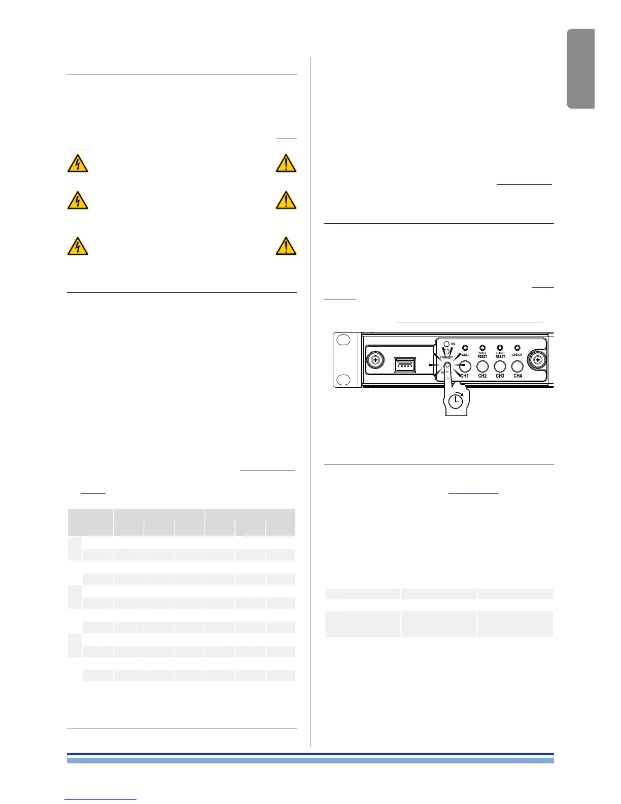
3 : 6.Switch ON/OFF
Once properly powered (power cord inserted, sectioning
breaker closed), the system can be either ON or in STANDBY
mode depending on its state at latest power off.
In order to toggle the amplier ON and STANDBY
keep pressed the power button for 3 seconds (see Panel
C, p. 5). Please consider that the operating condition
can be modied by the REMOTE ON and REMOTE OFF
conguration (see §3 : 9.Remote ON/OFF (standby mode)).
3 : 7.Energy save
The Smart Rails Management technology implemented in
the power supply unit allows to reduce the power consumption
when the input signal falls under a dened threshold.
Signal activity is monitored on the input section of the
amplier so that the system can resume normal operation
in a matter of milliseconds when an incoming signal is
detected on the channels. Once switched on, Energy Save
is active on each channel independently.
If the signal is missing for more than 30 minutes on all
channels, the auto standby is applied and the main PSU
is turned off to further save energy*. Normal operation is
resumed in a matter of milliseconds when an incoming
signal is detected on the channels.
In order to activate the Energy Save feature, locate the
NRG SAVE switch on the rear panel (see Panel D, p. 5)
and set it ON (high).
TAB. 1 shows the power consumption in idle mode when
the Energy save is either enabled or disabled.
Energy
Save
115 V
AC
mains 230 V
AC
mains
Current
Real
Power
Apparent
Power
Current
Real
Power
Apparent
Power
4804
OFF
0.45 A 32.3 W 74 VA 0.35 A 32.4 W 142 VA
AUTOSTBY
0.45 A 19 W 52 VA 0.46 A 20 W 106 VA
4804
DSP+D
OFF
0.5 A 33.6 W 76 VA 0.35 A 33.7 W 145 VA
AUTOSTBY
0.47 A 20 W 55 VA 0.57 A 21 W 131 VA
2404
OFF
0.40 A 31.4 W 69 VA 0.28 A 31.6 W 138 VA
AUTOSTBY
0.45 A 19 W 52 VA 0.45 A 19 W 104 VA
2404
DSP+D
OFF
0.45 A 32.7 W 70 VA 0.29 A 31.8 W 140 VA
AUTOSTBY
0.46 A 20 W 53 VA 0.46 A 20 W 106 VA
1204
OFF
0.40 A 31.4 W 69 VA 0.28 A 31.6 W 138 VA
AUTOSTBY
0.45 A 19 W 52 VA 0.45 A 19 W 104 VA
1204
DSP+D
OFF
0.45 A 33.6 W 70 VA 0.29 A 32.8 W 140 VA
AUTOSTBY
0.46 A 20 W 53 VA 0.46 A 20 W 106 VA
TAB. 1: Idle consumption.
3 : 8.Breaker save
In case the power grid is unable to provide enough
current to continuously drive the loads, or when the number
of attached amplier to the same AC mains is such that one
can reach the critical power absorption from the line, it is
possible to activate the Breaker Save feature.
When activated, the Breaker Save feature reduces
(halves) the maximum continuous current absorption from
the mains. This slightly reects on the overall performance
of the system reducing the available output power.
In order to activate the Breaker Save feature, locate the
BRK SAVE switch on the rear panel (see Panel D, p. 5)
and set it ON (high).
3 : 9.Remote ON/OFF (standby mode)
Remote ON/OFF is available through the dedicated
terminals on the rear panel (see Panel C, p. 5).
Both terminals respond to the differential voltage
between the contacts: a voltage difference in the range
5 V
DC
- 24 V
DC
triggers the control. Any voltage exceeding
28V
DC
may damage the input circuitry.
The couple of terminals act depending on the actual
state of the amplier, as shown in .
REMOTE ON REMOTE OFF AMPLIFIER STATE
Vdiff ≥ 5V Any Force Turn ON
Vdiff < 3V Vdiff ≥ 5V Force Turn OFF
Vdiff < 3V Vdiff < 3V
No Change
(Keep either standby
or in current state)
In order to remotely toggle between standard operating
and standby modes, the AC mains power must be
connected.
*Time out time is selectable via Armonìa in DSP+D Versions
FIG. 1: Keep pressed the power pushbutton
to toggle ON/STANDBY the amplifier.
English | 13
 Loading...