T Series | 41
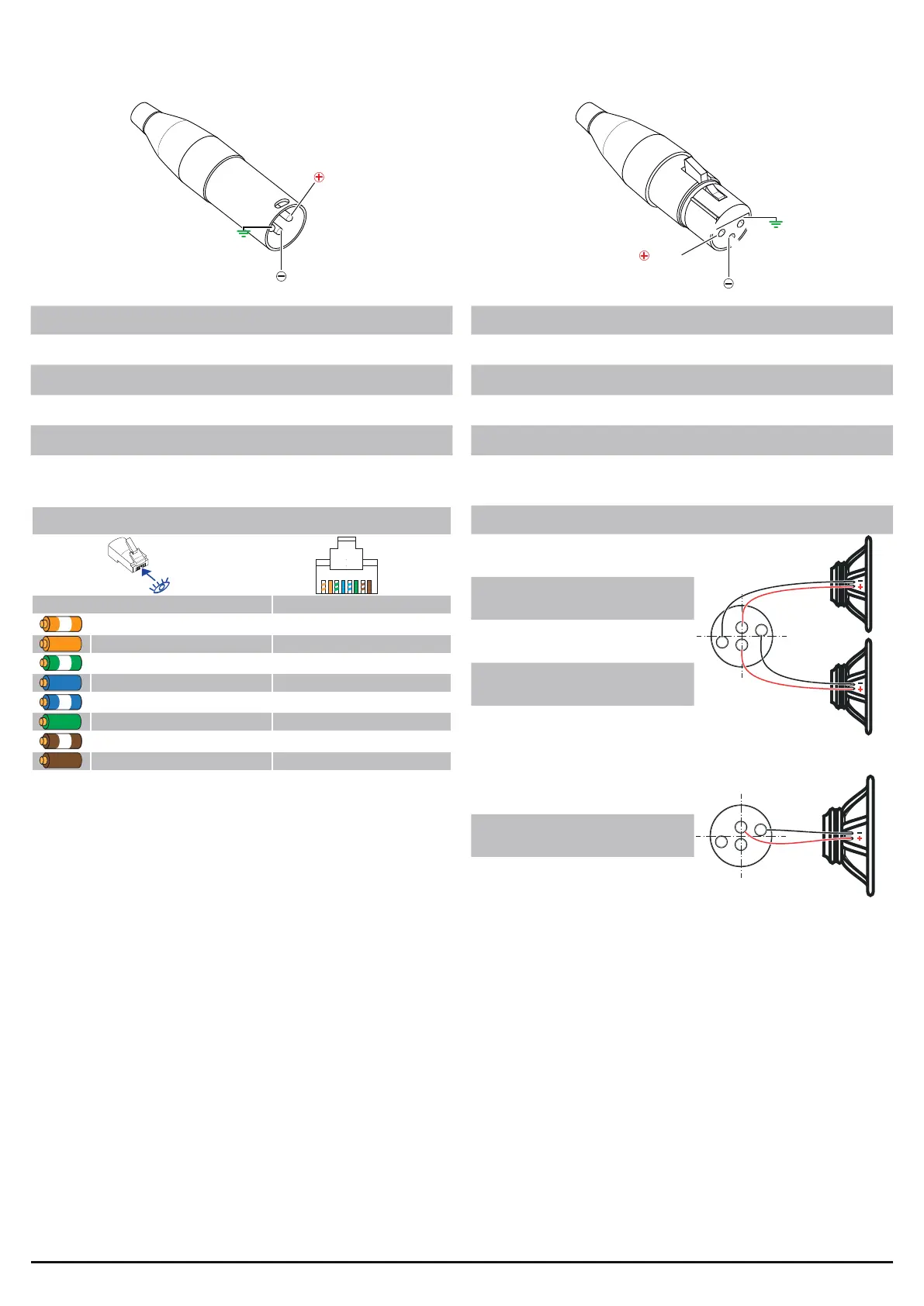
Pinouts
Network Connector RJ45 pinout
1 2 3 4 5 6 7 8
Color code (TIA/EIA-568-B) Pin
ORANGE / WHITE 1
ORANGE 2
GREEN / WHITE 3
BLUE 4
BLUE / WHITE 5
GREEN 6
BROWN / WHITE 7
BROWN 8
1
2
3
GND
HOT
COLD
GND
HOT
COLD
2
1
3
Analog/AES3 input XLR-M pinout
Pin# Terminal
1 Ground (GND)
2
3
Output NL4 Speakon-F pinout
Single Ended
speakON
connector
output
stage A
output
stage B
CHA +
A
B
Bridge-tied load
Two single-ended loads
CHB –
CHA –
A
B
speakON
connector
output
stage A
output
stage B
CHA +
CHB +
CHB –
CHA –
A
B
1+
2+
1–
2–
1+
2+
1–
2–
1+
1-
2+
2-
Analog/AES3 link XLR-F pinout
Pin# Terminal
1 Ground (GND)
2
3
Bridged
speakON
connector
output
stage A
output
stage B
CHA +
A
CHB +
B
Bridge-tied load
Two single-ended loads
CHB –
CHA –
A
B
speakON
connector
output
stage A
output
stage B
CHA +
CHB +
CHB –
CHA –
A
B
1+
2+
1–
2–
1+
2+
1–
2–
1+
2+
1–
2–
1+
2+
1–
2–
1+
2-