Model
1000
Installation and Operation Manual
Page
15
OFFICIAL 6/1/2001
H
OW
D
O
I …
CONNECT AN OUTPUT CONTACTOR?
When you use an output contactor with the Model 1000, you
MUST interlock the output contactor with the Emergency Stop.
You WILL damage the drive if you do not interlock it.
Requirements for the Model 1000 series are:
1. The contactor must close its main power contacts
BEFORE it enables the drive;
2. The contactor may only open its contacts AFTER
disabling the drive.
It is important to note that the contactor does not make
or break current.
The figure at left shows the connections for a 48VDC output
contactor (such as AEG part number SH-04.40-ODC, which is
available from
POWERTEC
).
In this configuration, the contactor energizes on a run
command and de-energizes ONLY on an emergency stop. The
contactor stays energized during normal stops.
POWERTEC
makes an optional track mount PC board (Part
# 156-012) for sequencing of contactors with AC coils.
DO NOT BREAK THE GROUND CONNECTION OR THE CABLE
CONNECTIONS WITH THE OUTPUT CONTACTOR.
H
OW
D
O
I …
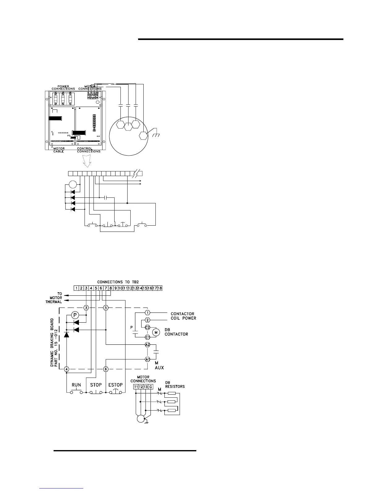
CONNECT DYNAMIC BRAKING?
You MUST interlock the contactor with the
Emergency Stop when using Dynamic Braking. You
will damage the drive and/or the resistor banks if
you do not properly interlock the contactor.
The requirements are:
1. The contactor must open the main power
contacts BEFORE the drive is enabled; AND
2. The contactor may only close its contacts
AFTER disabling the drive.
The AEG SH-04.13-ODC contactor is suitable
to the circuitry above. The figure on the left shows
the connections for using a POWERTEC 156-012
Contactor Control board to control a larger
contactor or a contactor with an AC coil.
In this configuration, the contactor energizes
when there is a run command and de-energizes
ONLY on an emergency stop. The contactor stays
energized during normal stops.
BLDC
MOTOR
T1
T2
T3
G
T1
T2
T3
M
181 2 3 4 5 6 7 814
TB2
MOTOR
THERMAL
M
M aux
RUN STOP
EMER
STOP
CONTACTOR
3 POLE N.O.
1 N.O. aux
48VDC COIL
@ 2.4 W
GND
9 10 11 12 13
JOG
6
CONTACTOR
3 POLE N.C.
1 N.O. AUX
COIL < 230VAC