Model
1000
Installation and Operation Manual
Page
31
OFFICIAL 6/1/2001
WHAT HAPPENS WHEN I …
GIVE THE START COMMAND TO THE MODEL 1000 ?
Before starting the Model 1000 drive, turn the Current Limit pot fully counter-clockwise, and the
speed reference command input, analog or digital, should be set to zero.
You must have +24VDC (all voltages are relative to TB1 terminal 16)
applied to TB2 terminal 7 (Emergency Stop input) before attempting to
RUN or JOG. You must maintain +24V on TB2 - 7 as long as you want to
run or jog.. Removing +24V from the Emergency Stop input will stop the
drive regardless of whatever other inputs may be energized.
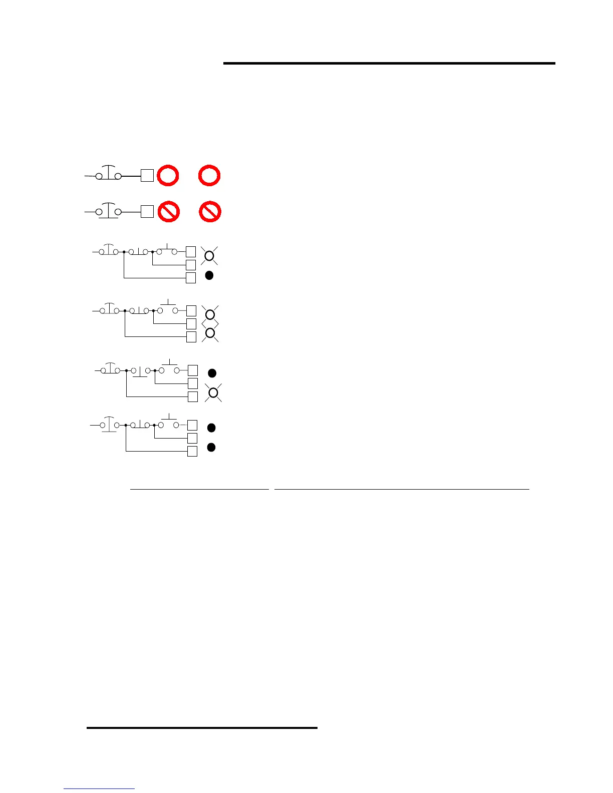
You must apply +24V to TB2 terminal 4 to start the
Model 1000 drive. When you energize TB2-4, even if the
Emergency Stop circuit is NOT energized, the RUN LED
on the Speed Controller board will light up and the normally
open RUN contact between TB2 terminals 1 and 2 will
close. If the Emergency Stop is closed, the drive will be in
the RUN mode as long as the +24V is maintained on TB2 -
4.
If you use a momentary contact to energize the RUN
input at TB2-4, then you must have +24V applied to TB2
terminal 5 to continue running, as illustrated in the drawing
at left. If you do not have +24V applied to TB2 - 5, then the
RUN LED will go off and the RUN contact will open as
soon as you let go of the START button.
If you press the STOP button in the drawing at left, or
otherwise remove +24V from TB2-5, the drive will go to the
ramp stop mode, i.e., the motor will coast or decelerate to
a stop and the drive shuts off.
To shut off immediately, open the Emergency Stop
button or otherwise remove +24V from TB2-7.
You may start the drive with the JOG input by applying +24 VDC to TB2 terminal 13. The JOG LED
will light. The RUN LED will NOT light up
. The RUN contact will NOT close at TB2 terminals 1 and 2.
The JOG mode should be initiated from the STOPPED condition. If the JOG input is energized while
in RUN mode, the JOG overrides the RUN mode. When the JOG input is released, the drive returns to
RUN mode (if it is still on) and accelerates to the speed commanded by the input speed reference.
In either JOG or RUN mode, an ENABLE REQUEST is generated, and the ENABLE LED should light
on the Current Controller board. There are several reasons why the LED may not light:
1. The ENABLE LED will not light if the BUS LED is not GREEN;
2. The ENABLE LED will not light if the EMERGENCY STOP input is not energized;
3. The ENABLE LED will not light if any trip LED on the Current Controller board is lighted:
• The OV/UV LED, indicating an over-voltage or under-voltage bus condition;
• The PL LED, indicating a power supply deficiency;
• The IOC LED, indicating excessive current going to the output transistors.
4. The ENABLE LED will not light if any of the ribbon cables is loose;
5. The ENABLE LED will not light if the RESET JUMPER is in the middle position.
Once the ENABLE LED is lit, turning the motor only requires the insertion of a speed reference.
E.STOP
E.STOP
CLOSED
OPEN
7
TB2
7
TB2
+24VDC
+24VDC
RUN
+
o
JOG
OR
RUN JOG
AND
START
STOP
OPEN
+24V
4
TB2
5
7
OPENCLOSED
RUN
ENABLE
E.STOP
EMERGENCY
STOP
START
STOP
E.STOP
CLOSED
+24V
4
TB2
5
7
CLOSEDCLOSED
RUN
ENABLE
START
+
+
+
E.STOP
START
STOP
CLOSED
+24V
4
TB2
5
7
OPENCLOSED
RUN
ENABLE
RUN
MODE
+
+
0
START
STOP
OPEN
+24V
4
TB2
5
7
OPENCLOSED
RUN
ENABLE
E.STOP
RAMP
STOP
0
+
0
0
0
0