7.5 kVA - 15 kVA UPS
Parallel for Redundancy System
User’s and Installation Manual
1012833
Revision 4
13
6.3 Power connections
The electrical planning and the UPS installation must be done by qualified personnel only.
WARNING!
The UPS contains high voltage and current which can injure or kill personnel
and damage equipment.
The customer has to supply the wiring to connect the UPS to power lines.
The power cables between UPS and parallel module is supplied with the parallel module.
The installation inspection and initial start up of the UPS system must be carried out by
service personel from the manufacturer or from an agent authorised by the manufacturer.
The UPS system has the following power connections:
3-phase and N and connection for rectifier inputs
3-phase and N and connection for bypass inputs for both UPSes and the parallel
module
3- phase and N connection between UPS and parallel cabinet
3-phase and N and connection for load output
+, - and connection for the battery
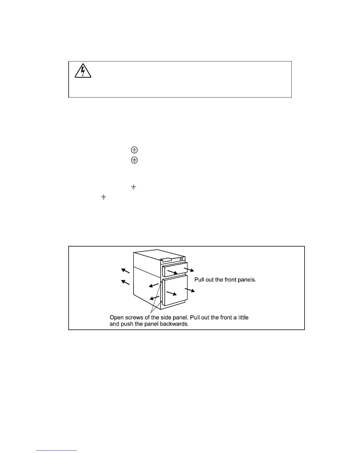
All input and output wiring of the UPS connects to the terminals located behind the left side
panel. Wiring can be routed through the cable entry at the bottom or back of the UPS cabinet.
All input and output wiring of the parallel module is connected to the terminals behind the
module door. Wiring is done from the bottom of the module.
Fig. 5a. Removing the front panels and opening the left side panel.