7.5 kVA - 15 kVA UPS
Parallel for Redundancy System
User’s and Installation Manual
1012833
Revision 4
23
8.2 Shutting down a UPS
The UPS unit does not have to be shut down at the end of each day. The units are
designed to cope with a continuous load from the day it is installed until a change is
needed in the backup battery bank.
In parallel for redundancy system it is possible to shut down one UPS and still get UPS
protected power for the load.
If both UPSes need to be shut down, but the load still needs to be powered, turn the
maintenance bypass switch of the parallel module to the BYPASS position according to
the section 8.4 of this manual.
Shutting down procedure:
Remove the front panels of UPS. Fig. 5a.
Turn the main switch S1 to
position
Turn the circuit breakers F1 and F2 to 0 position
The UPS stops supplying power and it will be disconnected internally from the
batteries.
NOTE!
High voltage is still present in some parts of the UPS and specially in the UPS output
terminals becauce of the parallel UPS.
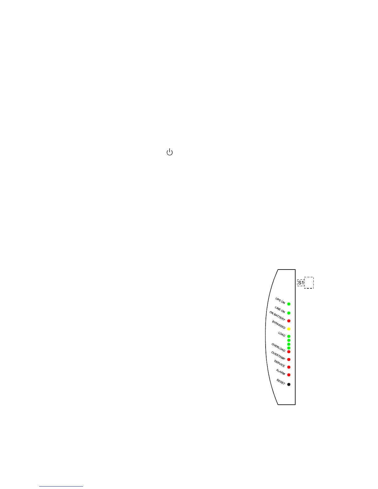
8.3 Control panel functions
The control panel shows the status of the operation and generates an audible alarm if the
user should be alerted. See figure 10.
LED LED is activated if:
UPS ON UPS operates normally providing
power to its outlets.
LINE ON Utility mains voltage is used for
feeding the load. When LED is off,
the utility mains is too low, too high
or missing or UPS is not synchronised
to input power lines.
ON BATTERY UPS is on battery operation.
If the LED is blinking, the battery voltage
is low and less than 2-3 minutes back-up
time left.
BYPASSED UPS is bypassed.
Fig.10. Control panel