7.5 kVA - 15 kVA UPS
Parallel for Redundancy System
User’s and Installation Manual
1012833
Revision 4
19
Table 4. RS232 connection (X100) for the computer, 9-pin female D-sub.
Table 5. RS232 connection (X101) for the modem, 9-pin male D-sub.
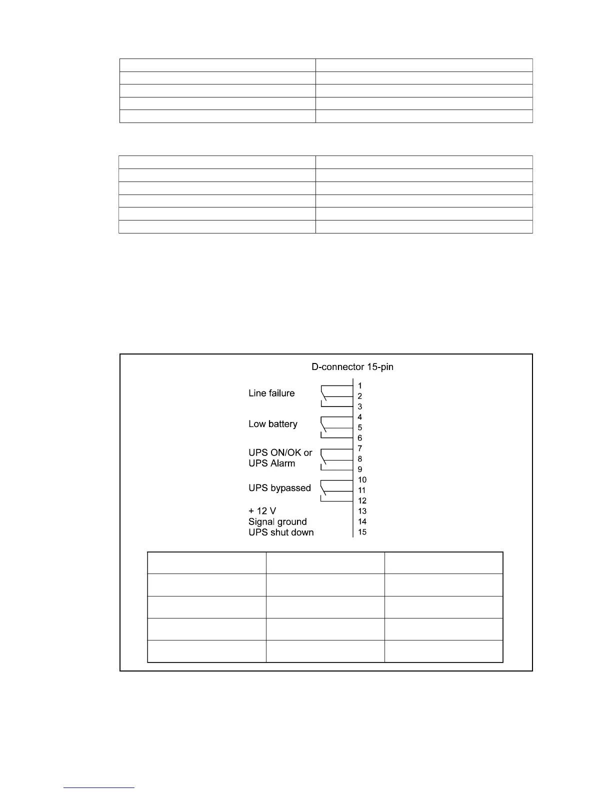
Potential free relay interface
This relay interface uses a 15-pin male D-sub connector (X102, see figures 5b). The
following information is available from these relays:
Pin 15 is the UPS shutdown input. User can send a high level for 5 seconds to turn off the
UPS until proper voltage returns. It is active only when the UPS is in battery operation.
Fig. 8. Relay interface of the UPS (X102).
1niPataddevieceR
2niPataddettimsnarT
4niPdnuorglangiS
8niPtuptuoCD
9niPdnuorgSPU
1niPdetcetedreirracataD
2niPataddevieceR
3niPataddettimsnarT
4niPydaerlanimretataD
5niPdnuorglangiS
7niPdnesotydaeR
onniP
detcennoc
etatsmetsyS
eruliafeniL
2-1
3-1
koeniL
eruliafeniL
yrettabwoL
5-4
6-4
lamronyrettaB
wolyrettaB
dessapybSPU
11-01
21-01
ylppusretrevnI
ylppusssapyB
roko/noSPU
mralASPU
9-7
8-7
ko/noSPU
mralaSPU