7.5 kVA - 15 kVA UPS
Parallel for redundancy System
User’s and Installation Manual
1012833
Revision 4
6
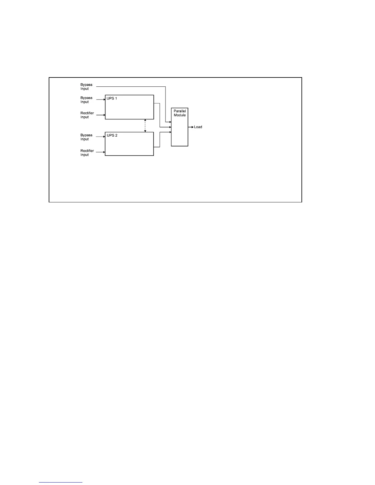
Figure 1 shows block diagram of the parallel for redundancy system. Parallel information
connection between UPS1 and UPS2 informs the other unit about bypass availability and
synchronisation. This parallel information between UPS1 and UPS2 is needed to be able
to use without any risk the bypass power lines.
Fig. 1. Block diagram of the parallel for redundancy system
Both UPSes are indentical having similar operation. UPS block diagram shown in fig. 2,
consists of several modules each having its own functions:
This UPS is a double conversion on-line UPS for protection of computer systems and
other intelligent devices such as measurement instruments and industrial automation
applications. It conditions the raw mains and supplies continuous, clean three-phase
power to the critical systems. While feeding the load the UPS also keeps the battery
constantly charged. If utility power fails, the UPS will continue to supply clean power
without any interruption at the UPS output.
If the power failure outlasts the backup time the UPS will shut down in order to prevent a
total discharge of the battery. When the line voltage is restored the UPS will start up again
automatically providing power to the critical load and charging the battery bank.
Transients on the mains are reduced by an input filter.
AC-power is rectified and regulated in the rectifier which provides the power to the
inverter and the battery charger to keep the battery bank fully charged.
The inverter converts the DC-power back to AC-power, which is delivered to
the load through the parallel module.
The static switch transfers the load to the bypass line when the inverter is
overloaded or the inverter is not able to feed the load. The transfer to the static bypass
as well as back to inverter mode happenes simultaneously in both UPS units.
The battery provides power to the load during a mains failure.
The battery charger keeps the battery fully recharged.