page no. 32 of 68
LX Range Users, Installation & Servicing Instructions Doc Ref M110 issue 1.0 Dec 2020.
6. Apply a bead of silicon sealant around the face of the
flange on the exhaust fan outlet tube that can be seen
from the outside of the heater. Place the flue socket on
the outside of the heater to mate with this flange and
clamp the two flanges together, on either side of the
heater panel using the screws provided. Ensure that the
silicon sealant has sealed between the two flanges.
7. Apply silicon sealant and refit blanking plates as
required to seal unused panel holes.
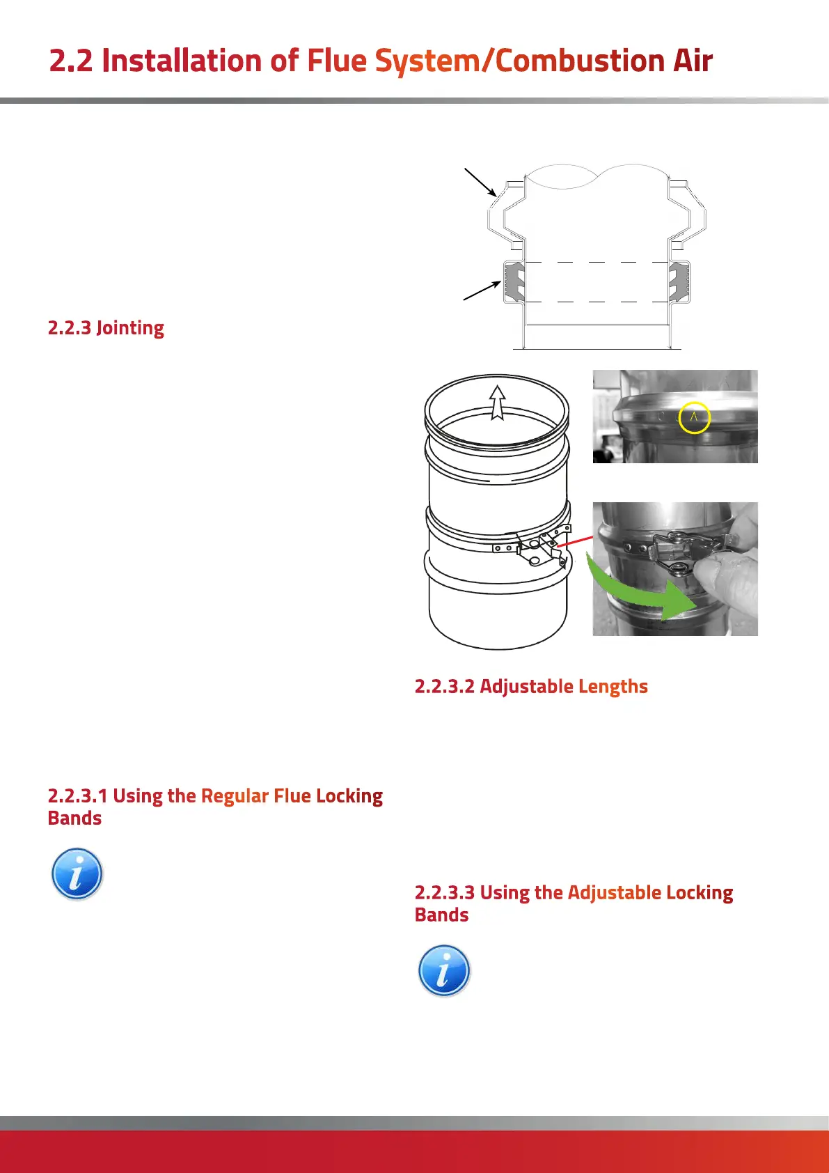
2.2.3 Jointing
The flue system is jointed by pushing the male end into
the female end of the proceeding component, and then
applying a Locking Band.
Each flue item comes complete with a factory bonded
elastomer seal which provides a secure grip to the male
end of the next flue component.
A seal lubricant gel can be used to facilitate ease of
installation and prevent potential damage of the seal
during installation
If shorter lengths of flue are required then Powrmatic
supply an adjustable length which provides adjustment
between 75-230mm.
In extreme circumstances, and where an adjustable
length cannot be used, flue may be cut but only the male
end should be removed to retain the flue seal. The cut end
must be clean and free from burrs before fitting into the
seal ring of the female end. As the locking band cannot
be used, we would suggest fixing the joint by a ring of
sealant and fixed using three self tapping screws, being
careful not to pierce the inner seal ring
2.2.3.1 Using the Regular Flue Locking
Bands
NOTE: The locking band has a defined profile
which will only allow for the toggle to be
closed one way. An indication arrow marked on
the face of the clamp must be pointing
towards the inserted male end.
Therefore when assembling the band onto the flue, the
toggle must snap to the right (see following diagram).
Cross sectional area detailing sealing arrangement.
Female socket
Male end
Seal
Ring
Locking
Band
Female end
Male end
Toggle must snap to the right
Arrow MUST be pointing
towards the inserted male
end of the flue
Female end
Male end
2.2.3.2 Adjustable Lengths
The Adjustable Length consists of a slip section of flue, the
lower non-beaded end of which is designed preferably to
be located into a standard length. It can also be inserted
into the female end of other components, but however
applied, must engage to a depth equivalent to at least half
of the diameter of the flue being used. Adjustment from
75mm to 230mm. Where pressure and moisture resistance
are required a special Locking Band & Seal is required to
make the joint.
2.2.3.3 Using the Adjustable Locking
Bands
NOTE: The locking band has a defined profile
which will only allow for the toggle to be
closed one way. An indication arrow marked on
the face of the clamp must be pointing
towards the inserted male end.
Therefore when assembling the band onto the flue, the
toggle must snap to the right (see following diagram).
2.2 Installation of Flue System/Combustion Air

 Loading...


