page no. 33 of 68
LX Range Users, Installation & Servicing Instructions Doc Ref M110 issue 1.0 Dec 2020.
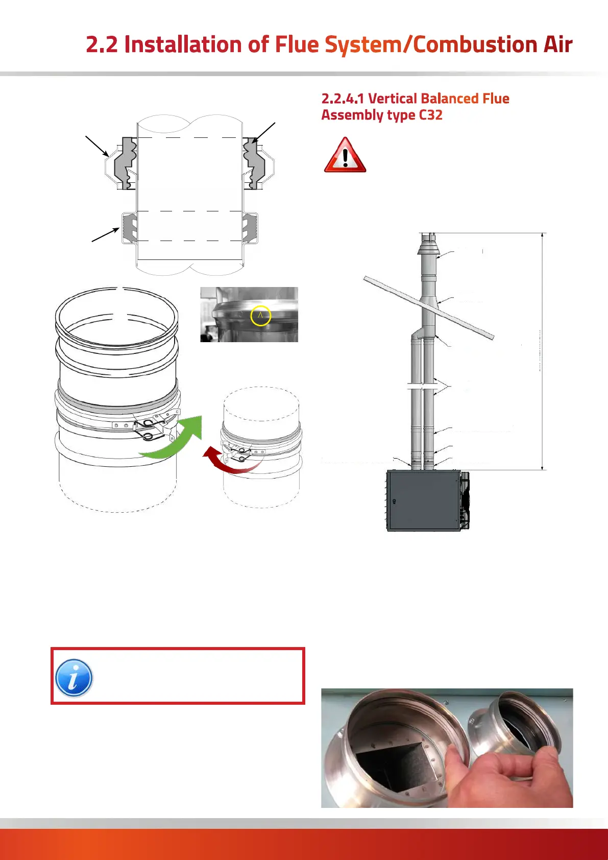
Cross sectional area detailing sealing arrangement.
Slip Section
Inner Tube
Outer Tube
Adjustable
Locking
Band
Seal
Ring
Locking
Band
Seal
Arrow MUST be pointing
towards the inserted male
end of the flue
Outer tube
Inner Slip
Slip Section
Inner Tube
Outer Tube
CORRECT METHOD
INCORRECT METHOD
Locate the seal over the socketed female end of the outer
tube or component female end before inserting the male
end, and then pull the seal up so that the angled notch on
its inside locates over the turned end of the female socket
as shown on the previous page.
A seal lubricant gel can be used to facilitate ease of
installation and prevent potential damage of the seal
during installation.
NOTE: As each installation is different,
the following descriptions and sketches
are shown TYPICALLY.
2.2.4.1 Vertical Balanced Flue
Assembly type C32
IMPORTANT: The maximum length for a
balanced flue system is 6 metres.
The maximum length of flue is subsequently
shortened if bends are added to the planned
flue run. 90° bends are equivalent to a 1m length and
45° bends are equivalent to a 0.5 m length.
Fig 1a . Typical individual system - Type C32 vertical
Terminal
Single to Twin Adaptor
Lengths
Adjustable Lengths
Combustion Air Socket
Flue Socket
Flashing
Condsensate
Drain Lengths
Maximum 6m, Minimum 80Ø=1480mm; 100Ø=1560mm; 130Ø=1560mm
Using the glue and screws provided, attach the silicon
flashing into place over the hole in the roof, then cut the
flashing to match the size of flue.
Insert the vertical terminal through the roof to give the
correct height above the roof to relevant regulations or
rules in force. Secure using the terminal securing bracket.
Attach the terminal extension length (not required on
Ø130mm) and the terminal adaptor (ski boot).
Check that the spigots on the heater contain their seals.
2.2 Installation of Flue System/Combustion Air

 Loading...


