page no. 35 of 68
LX Range Users, Installation & Servicing Instructions Doc Ref M110 issue 1.0 Dec 2020.
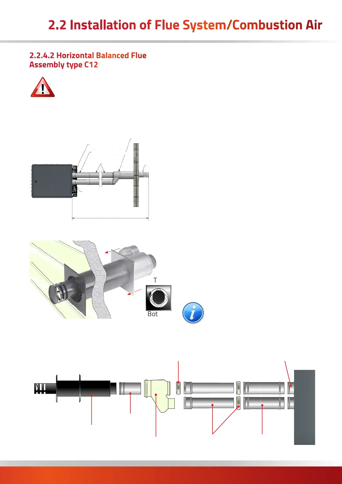
Heater
Horizontal Wall Terminal
Adjustable Length
Locking Band
Adapter (Ski Boot)
Connection Length
Adjustable Lengths
c/w Locking Bands
Heater
Spigots
250mm
Flue Lengths
Typical Horizontal Balanced Flue
type C12 - exploded view
2.2.4.2 Horizontal Balanced Flue
Assembly type C12
IMPORTANT: The maximum length for a
balanced flue system is 6 metres.
The maximum length of flue is subsequently
shortened if bends are added to the planned
flue run. 90° bends are equivalent to a 1m length and
45° bends are equivalent to a 0.5 m length.
Fig 1b . Typical individual system - Type C12 vertical
Flue Socket
Adjustable Lengths
Lengths
Terminal
Combustion Air Socket
Single to Twin Adaptor
Maximum 6m, Minimum 980mm
Insert the horizontal terminal through the wall, and secure
using the wall securing plate.
Top
Bottom
Attach the terminal extension length (not required on
Ø130mm) and the terminal adaptor (ski boot).
Check that the spigots on the heater contain their seals.
Slide a 250mm length fully into the exhaust air spigot and
another into the combustion air spigot of the heater (a
smear of paraffin will help ease fitting).
Place an adjustable length locking band onto each end
of the condense and 250mm standard length ensuring
the rubber gasket is the correct way round (see section
2.2.3.3). Do not tighten at this stage.
Slide an adjustable length section into each end of the
250mm lengths. Allow a suitable distance for each
adjustable length to slide backwards - to release the flue
in the event that the flue needs to be separated in future.
Extra lengths of standard flue can now be added between
the adjustable length and the terminal adaptor (ski boot) if
required (not shown below). Clamp with locking bands.
Prior to connection to the terminal adaptor, place an
adjustable length locking band onto the end of the exhaust
flue pipe only.
Ensure that the exhaust air connects to the internal tube
of the terminal adaptor (heal of the ski boot) and the fresh
air inlet connects to the outer flue of the terminal adaptor
(toe of the ski boot).
Clamp the adjustable length locking band onto the exhaust
flue connection of the terminal adaptor (ski boot).
Once all flue components are correctly in place, lock the
adjustable length locking bands back at the adjustable
length sections.
NOTE: Refer to the following typical
breakdown sketch to aid with the above
procedures.
2.2 Installation of Flue System/Combustion Air

 Loading...


