page no. 36 of 68
LX Range Users, Installation & Servicing Instructions Doc Ref M110 issue 1.0 Dec 2020.
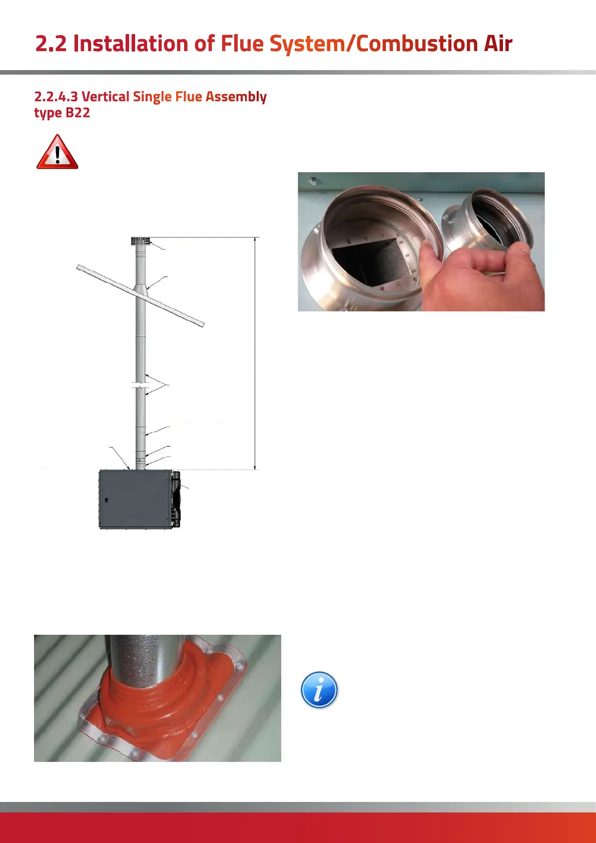
2.2.4.3 Vertical Single Flue Assembly
type B22
IMPORTANT: The maximum length for a
balanced flue system is 12 metres.
The maximum length of flue is subsequently
shortened if bends are added to the planned
flue run. 90° bends are equivalent to a 1m length and
45° bends are equivalent to a 0.5 m length
Fig 2a. Typical Exhaust only system -Type B22 vertical
Terminal
Flashing
Lengths
Adjustable Lengths
Flue Socket
Condsensate
Drain Lengths
Maximum 12m, Minimum 80Ø=1480mm; 100Ø=1560mm; 130Ø=1560mm
Option 1:
Combustion Air Entry
(fitted with inlet grille)
Option 2:
Combustion Air Entry
(fitted with inlet grille)
Using the glue and screws provided, attach the silicon
flashing into place over the hole in the roof, then cut the
flashing to match the size of flue.
Insert the vertical terminal through the roof to give the
correct height above the roof to relevant regulations or
rules in force. Secure using the terminal securing bracket.
Place a vertical terminal into the open end and clamp into
place using a locking band. (This locking band may be very
tight!, see section 2.2.3.1 for correct installation).
Check that the exhaust air spigot on the heater contains a
seal.
Slide a condense length fully into the exhaust air spigot (a
smear of paraffin will help ease fitting).
Place an adjustable length locking band onto each end of
the condense and 250mm standard length ensuring
the rubber gasket is the correct way round (see section
2.2.3.3). Do not tighten at this stage.
Slide an adjustable length section into the end of the
250mm standard length.
Allow a suitable distance for the adjustable length to slide
backwards - to release the flue in the event that the flue
needs to be separated in future.
Extra lengths of standard flue can now be added between
the adjustable length and final flue connection.
Prior to connection to the final piece of flue, place a locking
band onto the end of the flue pipe.
Clamp the flue locking band. (This locking band may be
very tight!, see section 2.2.3.1 for correct installation).
Once all flue components are correctly in place, lock the
adjustable length locking band back at the adjustable
length section.
NOTE: Refer to the following typical
breakdown sketch to aid with the above
procedures.
2.2 Installation of Flue System/Combustion Air

 Loading...


