page no. 37 of 68
LX Range Users, Installation & Servicing Instructions Doc Ref M110 issue 1.0 Dec 2020.
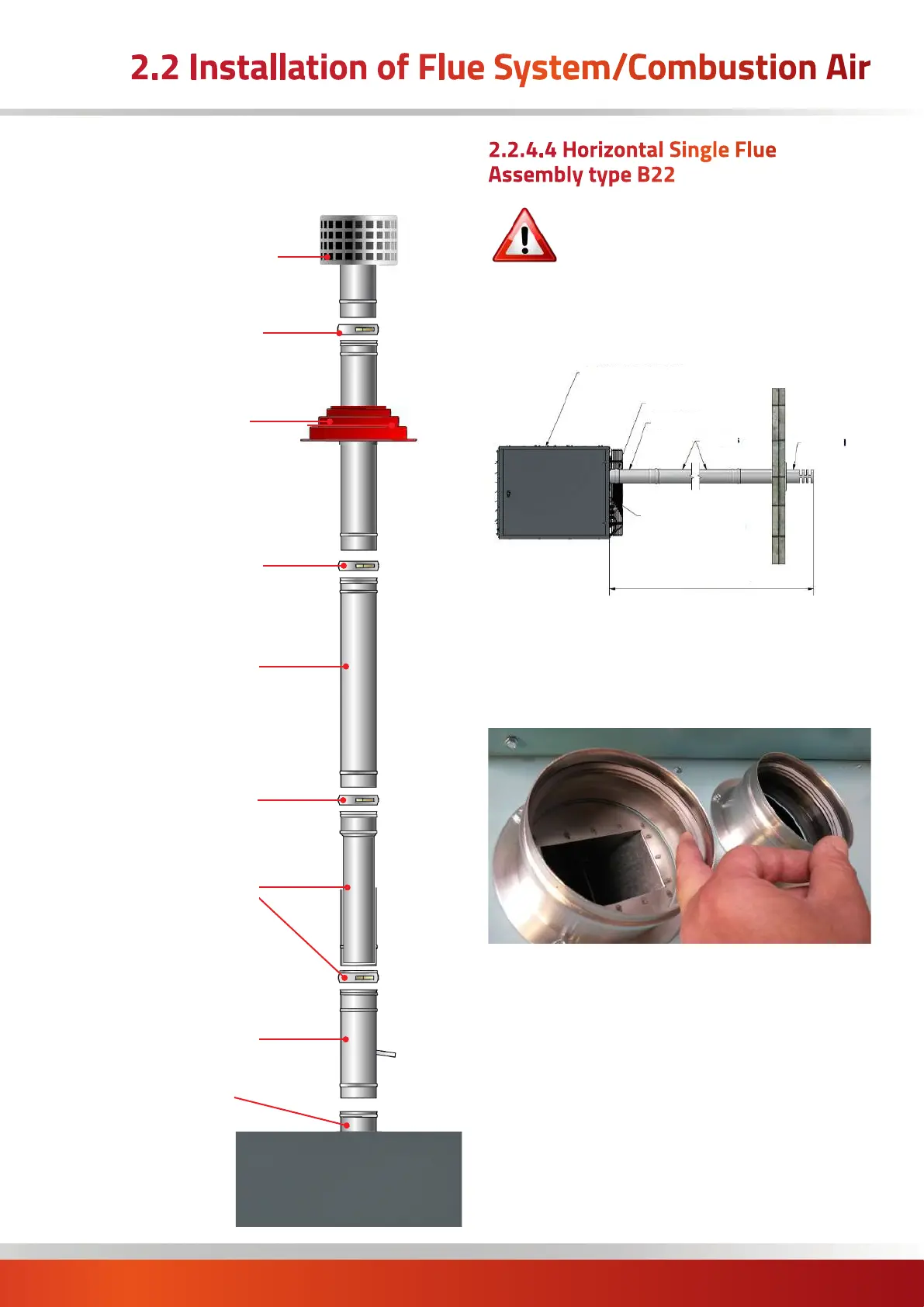
Vertical Roof Terminal
Silicone Flashing
Additional Flue
Lengths (as required)
Extra Locking Bands
(as required)
Heater Spigot
Locking Band
Locking Band
Condensate Length
Heater
Adjustable Length
c/w Locking Band
Typical Vertical Balanced Flue
type B22 - exploded view
2.2.4.4 Horizontal Single Flue
Assembly type B22
IMPORTANT: The maximum length for a
balanced flue system is 12 metres.
The maximum length of flue is subsequently
shortened if bends are added to the planned
flue run. 90° bends are equivalent to a 1m length and
45° bends are equivalent to a 0.5 m length
Fig 2b. Typical Exhaust only system - Type B22 horizontal
Flue Socket
Adjustable Lengths
Lengths
Terminal
Option 1: Combustion Air Entry
(fitted with inlet grille)
Maximum 12m
Option 2:
Combustion Air Entry
(fitted with inlet grille)
Insert the horizontal terminal through the wall, and secure
using the wall securing plate.
Check that the exhaust air spigot on the heater contains a
seal.
Clamp the flue locking bands. (These locking bands may
be very tight!, see section 2.2.3.1 for correct installation).
Place an adjustable length locking band onto each end of
the condense and 250mm standard length ensuring
the rubber gasket is the correct way round (see section
2.2.3.3). Do not tighten at this stage.
Slide an adjustable length section into the end of the
250mm length.
Allow a suitable distance for the adjustable length to slide
backwards - to release the flue in the event that the flue
needs to be separated in future.
2.2 Installation of Flue System/Combustion Air

 Loading...


