Section VI. Function Parameter Description
Motor’s output frequency under rated state.
b00~b04 are the motor’s nameplate parameters which touch the
precision.Set the parameters according to the motor’s nameplate.
Excellent vector control performance requires exact motor parameters.
Exact parameters are base on the correct setting of motor’s rated
parameters.
To assure the control performance, please match the right motor as per the
inverter’s standard, motor rated currentis limited between 30%~120% of
inverter rated current.
b05: motor un-load current factory setting: (y07×40%)A
The un-load current, and affects the degree of the slip compensation
directly.
The factory value is decided by power and default value is y07×40%.
b06: stator resistor factory setting: 0.000ohm
The stator resistor, when b13 is 1,the system scales automatically.
b07: rotor resistor factory setting: 0.000ohm
The rotor resistor, when b13 is 1, the system scales automatically.
b08: leakage inductance factory setting: 0.0mH
The leakage inductance of motor’s coil winding, when b13=1, system
measures automatically.
b09: mutual inductance factory setting: 0.0mH
The mutual inductance of motor’s coil winding, when b13=1, system
measures automatically.
b05~b09 is the motor’s basic electric parameters, these parameters is
essential to achieve vector control calculation.
When b01 is set, b05~b09 would automatically reset to the defaulted
standard Y series 4 poles asynchronism motor’s parameters. Inverter could
get the motor parameters without automatic parameters setting.
If the inverter could not meet with the requirement, use b13 motor
parameters setting to get the exact motor parameter. If the right motor
parameters are available, it could be input manually.
*b10~b13: Reserved
b14: Rotate speed display plus factory setting: 100.0%
Adjust the display of motor’s actual running speed, refer to F00 monitor
select: 6 Actual motor speed.
b15: Reserved factory setting: 0
b16: Reserved factory setting: 0
b17: Reserved factory setting: 0
Section VII. Fault Diagnosis and Solutions
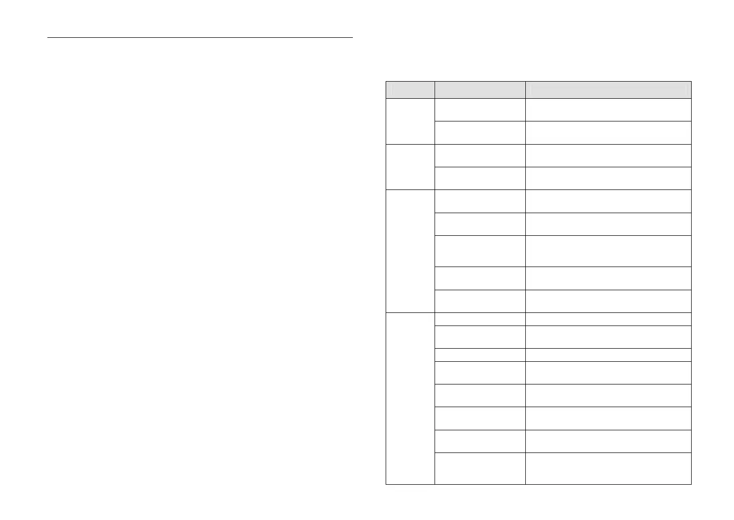
Problems
Possible causes Solutions
Control mode setting is
wrong
Check F05.
not control
Frequency setting is
wrong
Check F04.
Control mode setting is
wrong
Check F05.
speed
Frequency setting is
wrong
Check F04.
LED monitor indicates
error message
No voltage exists between
terminals P and N.
Check the voltage at R,S or T and charging
circuit.
U, V or W terminals
produce no output or
abnormal output.
Check the control mode and frequency
parameter. Check the terminal condition if it is
operated by an external terminal.
Re-start after powering
down or free run
Remember the set operating state.
The
motor
does
not
rotate
Too much load on the
motor
Check and lower the load.
fault display OC-P System is disturbed or instant over current
fault display OC-C
OC signal from current self-inspected citcuit
impact
fault display OC-FA OC signal from drive circuit
fault display OC-2
Output over current, and current exceed 2 times
of motor’s rated current.
Over current during
acceleration
Reset or modify the parameters of the functions
F09, F18, F19.
Over current during
deceleration
Reset or modify the parameters of the functions
F10, F20, F21.
Over current during
operation
Check the load change and eliminate it.
Over current
OC
Over current during
starting or operation from
time to time
Check if there is slight short circuit or grounding.
 Loading...

